Device and method for reconstruction of osseous skeletal defects

a technology for osseous skeletal defects and medical devices, applied in the direction of prosthesis, shoulder joints, ligaments, etc., can solve the problems of high high risk of infection and other complications of allograft prosthetic composites, and the inability to repair osseous skeletal defects, etc., to achieve the effect of facilitating the restoration of bone loss

Inactive Publication Date: 2005-01-13
JAMALI AMIR ALI
View PDF8 Cites 57 Cited by
  • Summary
  • Abstract
  • Description
  • Claims
  • Application Information

AI Technical Summary

Benefits of technology

[0019] The present invention provides an implantable device comprising a prosthesis and a flexible member attached to the prosthesis by means of one or more attachment members, where the flexible member is arranged around the prosthesis to form a cavitary space. The cavitary space is then filled with a variety of osteoconduc

Problems solved by technology

In the past, skeletal defects have required amputation due to the associated “flail extremity” which prohibited weightbearing due to skeletal insufficiency and lack of effective muscle power.
However, these have been associated with high rates of infections, non-unions, accelerated arthritis, and mechanical complications.
These allograft prosthetic composites (APC) were associated with high risks of infection and other complications.
Massive osteoarticular allografts and APC's have a tremendous disadvantage due to some residual antigenicity and the slow incorporation of the allograft bone by host bone.
The process termed “creeping substitution”, whereby the allograft bone is replaced by host bone in an appositional fashion, leads to overall weakening of the graft.
These prostheses, however, have several problems, including their large size, the high torques at the host-prosthesis interface, and risks of dislocation due to inadequate soft tissue attachments to the metal prosthesis.
The common complications with the technique relate to the loss of fixation due to fracture of the host bone or lack of containment and interlock of the ca

Method used


Image

  • Device and method for reconstruction of osseous skeletal defects
  • Device and method for reconstruction of osseous skeletal defects
  • Device and method for reconstruction of osseous skeletal defects

Examples


example 1

[0057] Femoral Resection

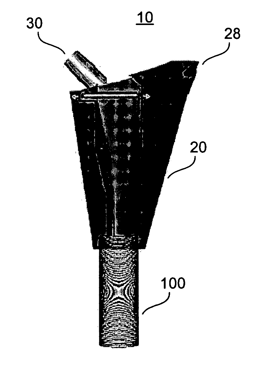
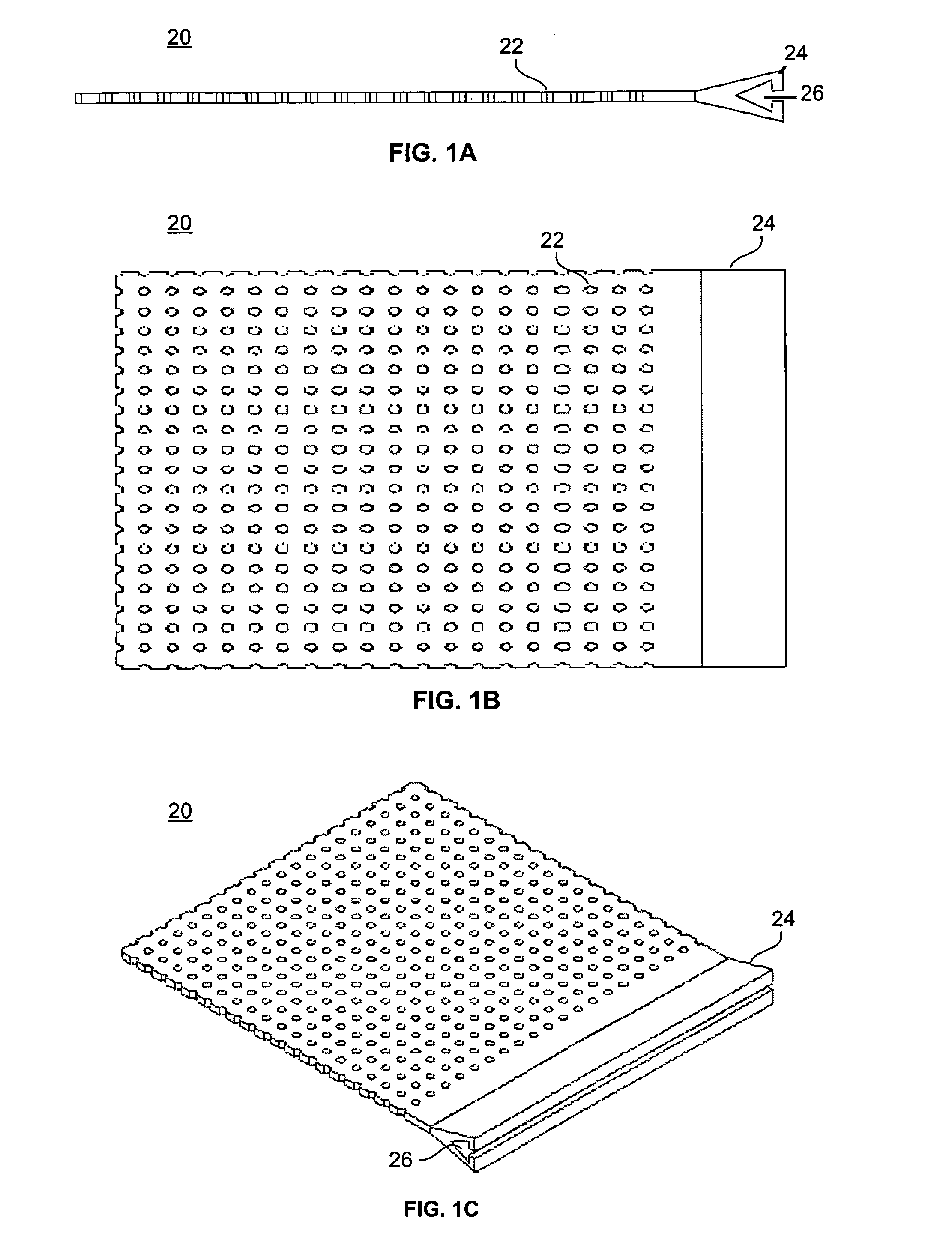
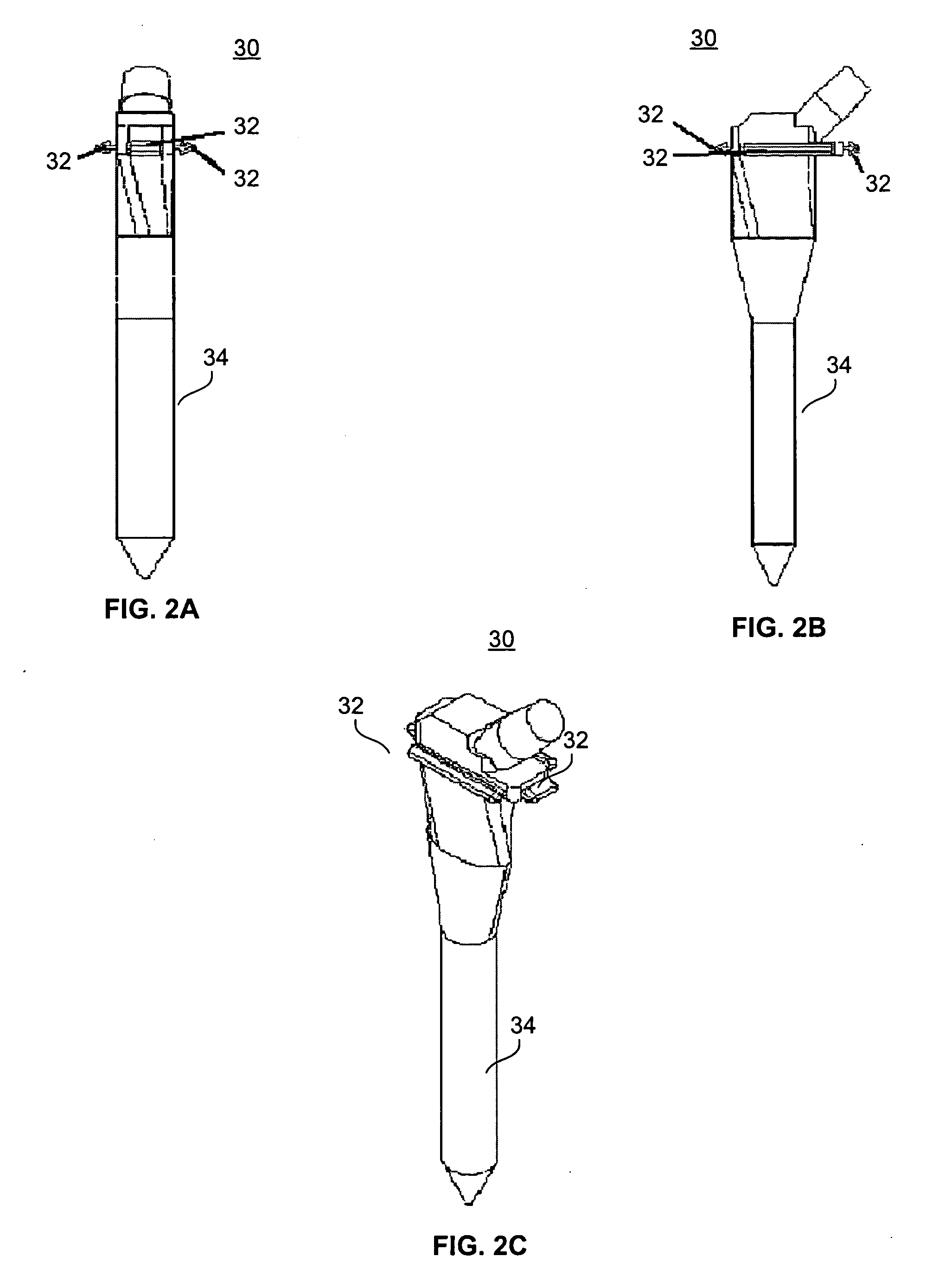
[0058] With reference to FIGS. 2 and 3, the present invention is utilized in resection of a proximal femoral osteosarcoma in a 15 year old male. FIGS. 2A through 2C illustrate a femoral prosthesis 30 of the present invention, and FIGS. 3A through 3D illustrate an implantable device 10 comprising the femoral prosthesis 30 surrounded by a flexible member 20. The implantable device 10 is used to reconstruct the proximal femur of a patient (not shown) in a five-step process. This process is adaptable for use, as will be evident to those of skill in the art, within any of the large joints including the hip, knee, shoulder, elbow, and ankle.

[0059] First, a prosthesis 30 is selected for use, with consideration given to the appropriate height of the stem 34 in order to achieve adequate leg length and soft tissue tension in the patient. The prosthesis 30 is provided with one or more attachment members 32, which are placed circumreferentially around the proximal end ...

example 2

[0064] Acetabular Reconstruction

[0065] With reference to FIG. 4, the present invention is used to treat a large superior defect 102 of the acetabulum 100 in the case of hip dysplasia or in the revision setting. FIG. 4A shows a porous surface uncemented cup prosthesis 30. FIG. 4B depicts a patient's acetabulum 100 with a large superior dome defect 102. As shown in FIG. 4C, the cup 30 is fixed to the residual acetabulum using acetabular screws, or a combination of modular cup attachments for screw fixation to the ilium, ischium, and pubis.

[0066] The residual bone loss is reconstituted by attachment of the flexible member 20 to the margins of the cup 30 with attachment members 32, as shown in FIG. 4D, and by filling the resultant cavitary space with bone graft material, as described in Example 1. This bone graft has the potential to mature into a vascularized bed that can grow into the porous surface of the prosthesis and also facilitate any future acetabular revision surgeries. The ...

example 3

[0067] Total Knee Arthroplasty

[0068] With reference to FIGS. 5 and 6, a total knee arthroplasty with a comminuted supracondylar fracture with major bone loss is treated with a long press-fit intramedullary revision femoral component embedded in the residual femoral diaphysis. FIGS. 5A through 5D illustrate a femoral prosthesis 30 of the present invention, and FIGS. 6A through 6C illustrate an implantable device 10 comprising the femoral prosthesis 30 surrounded by a flexible member 20. The implantable device 10 is used to reconstruct the distal femur of a patient (not shown) in a multi-step process.

[0069] The process described in Example 1 is adapted for use on the distal femur, wherein first a prosthesis 30 is selected for use, with consideration given to the appropriate height and circumference of the stem 34. The prosthesis 30 is provided with one or more attachment members 32, to which the flexible member 20 is attached. The proximal margins of the flexible member 20 are fixed...


PUM

PropertyMeasurementUnit
Flexibilityaaaaaaaaaa
Areaaaaaaaaaaa
Bioabsorbableaaaaaaaaaa

Abstract

A device for the reconstruction of skeletal defects with a flexible member, which is preferably resorbable, attached to a rigid structural prosthesis such as a dental implant, an orthopedic prosthetic implant, or an artificial disc implant. The cavitary space surrounded by the flexible member is filled with osteoconductive and/or inductive materials which eventually matures into bone. The prosthesis is supported by the bed of graft material surrounding it and is gradually unloaded as the bed matures into solid bone. The fixation of the prosthesis into native bone depends on the specific implant and the anatomic area of its use. The flexible member is secured to the margins of the prosthesis using rails, runners, sutures, or other attachment devices that prevent the escape of the bone graft and maintain an initial column of support for the implant.

Description

[0001] This application claims the benefit of U.S. Provisional Application No. 60 / 478,465, filed Jun. 16, 2003, which is herein incorporated by reference in its entirety.BACKGROUND [0002] 1. Field of the Invention [0003] The present invention relates generally to implantable medical devices for the treatment of osseous skeletal defects, and methods for their use. [0004] 2. Background of the Invention [0005] In the past, skeletal defects have required amputation due to the associated “flail extremity” which prohibited weightbearing due to skeletal insufficiency and lack of effective muscle power. Early in the twentieth century, Lexer popularized the transplantation of large human joint (allografts) for such problems. However, these have been associated with high rates of infections, non-unions, accelerated arthritis, and mechanical complications. With the advent of hip prosthetics as developed by Austin Moore's proximal femoral prosthesis in the 1940's and John Chamley's low friction...

Claims


Application Information

Patent Timeline
IPC IPC(8): A61B17/00A61B17/06A61C8/00A61FA61F2/00A61F2/02A61F2/08A61F2/28A61F2/30A61F2/34A61F2/36A61F2/38A61F2/40A61F2/42
CPCA61F2/0811A61C8/0006A61F2/2846A61F2/30734A61F2/34A61F2/36A61F2/3662A61F2/367A61F2/3676A61F2/3804A61F2/3859A61F2/389A61F2/40A61F2/4202A61F2002/2817A61F2002/2835A61F2002/30062A61F2002/30133A61F2002/30153A61F2002/30224A61F2002/30383A61F2002/30738A61F2002/30785A61F2002/30838A61F2002/30878A61F2002/30909A61F2002/3096A61F2002/3429A61F2002/3625A61F2210/0004A61F2220/0025A61F2230/0015A61F2230/0019A61F2230/0069A61F2310/00293A61B17/06166A61B2017/00004A61F2/2803
Inventor JAMALI, AMIR ALI
Owner JAMALI AMIR ALI
Why Eureka
Try Eureka