Radiation detector

a detector and radiation technology, applied in the field of radiation detectors, can solve the problems of more radiation going through the scintillator, and achieve the effects of deteriorating sensitivity, and reducing the size of the scintillator

Inactive Publication Date: 2005-01-20
NIHON MEDI PHYSICS CO LTD +2
View PDF6 Cites 21 Cited by
  • Summary
  • Abstract
  • Description
  • Claims
  • Application Information

AI Technical Summary

Benefits of technology

In the radiation detector, the sensitivity is deteriorated as the size of the scintillator is reduced. When the radiation goes through the scintillator, there is no emission of light generated. In other words, there is more possibility of the radiation going through the scintillator as the scintillator becomes smaller and the sensitivity becomes deteriorated. In the radiation detector of the present invention, while miniaturizing the scintillator to be able to be inserted into blood vessels, fine convexoconcaves are formed on the peripheral surface for suppressing the sensitivity deterioration due to the reduction of the size. Thereby the reflection of light emitted from inside the scintillator is diffused on the surface of the scintillator to be effectively guided to the optical fiber.

Problems solved by technology

In other words, there is more possibility of the radiation going through the scintillator as the scintillator becomes smaller and the sensitivity becomes deteriorated.

Method used


Image

  • Radiation detector
  • Radiation detector
  • Radiation detector

Examples


example 1

Effects of the cases where the peripheral surface of the scintillator was formed to be a specular surface and where it was formed to be a diffused reflex surface (with fine convexoconcaves) were examined. In order to effectively investigate the effects of the surface treatment, a plastic scintillator with the diameter of 3 mm and the length of 15 mm was used. Optical fiber was connected to the basal end face of the scintillator and photomultipliers were connected to the optical fiber. Beta-ray (90Sr-90Y) was used as the radiation source and the radiation source was moved by a collimator with the diameter of 1 mm made of a radiopaque substance from the side face of the scintillator to the axial direction. The photomultiplier pulse height maximum value at this time was measured by a multi-channel analyzer for measuring the channel of the maximum wave. The results of the measurement are shown in FIG. 5 to FIG. 7. The spectral diagrams A to J in FIG. 5 and FIG. 6 show the pulse height ...

example 2

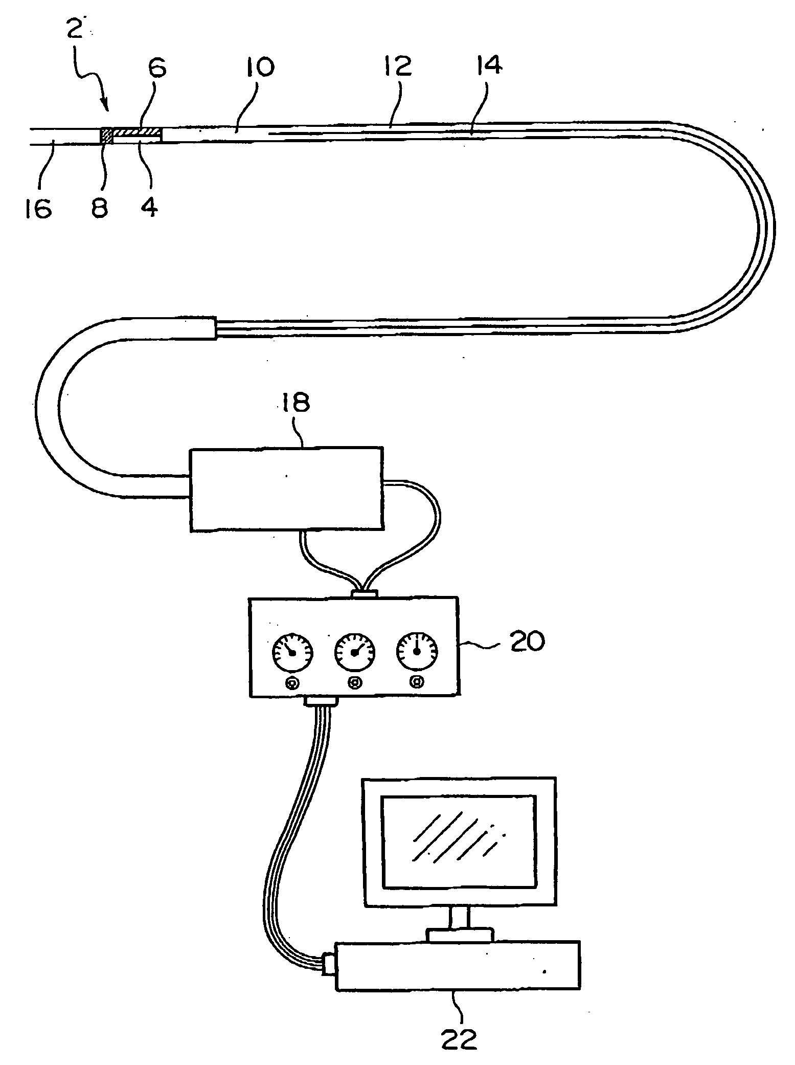
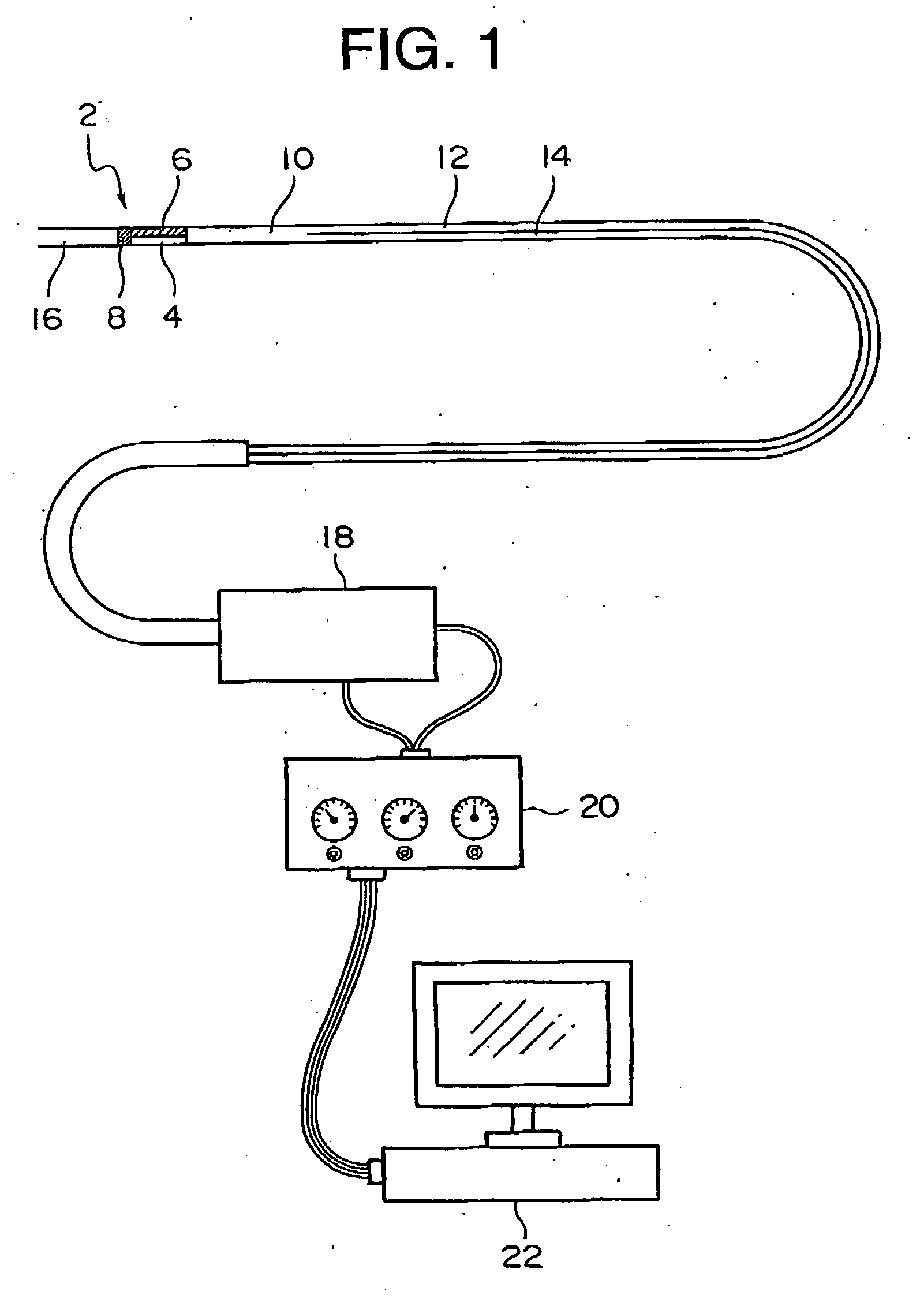
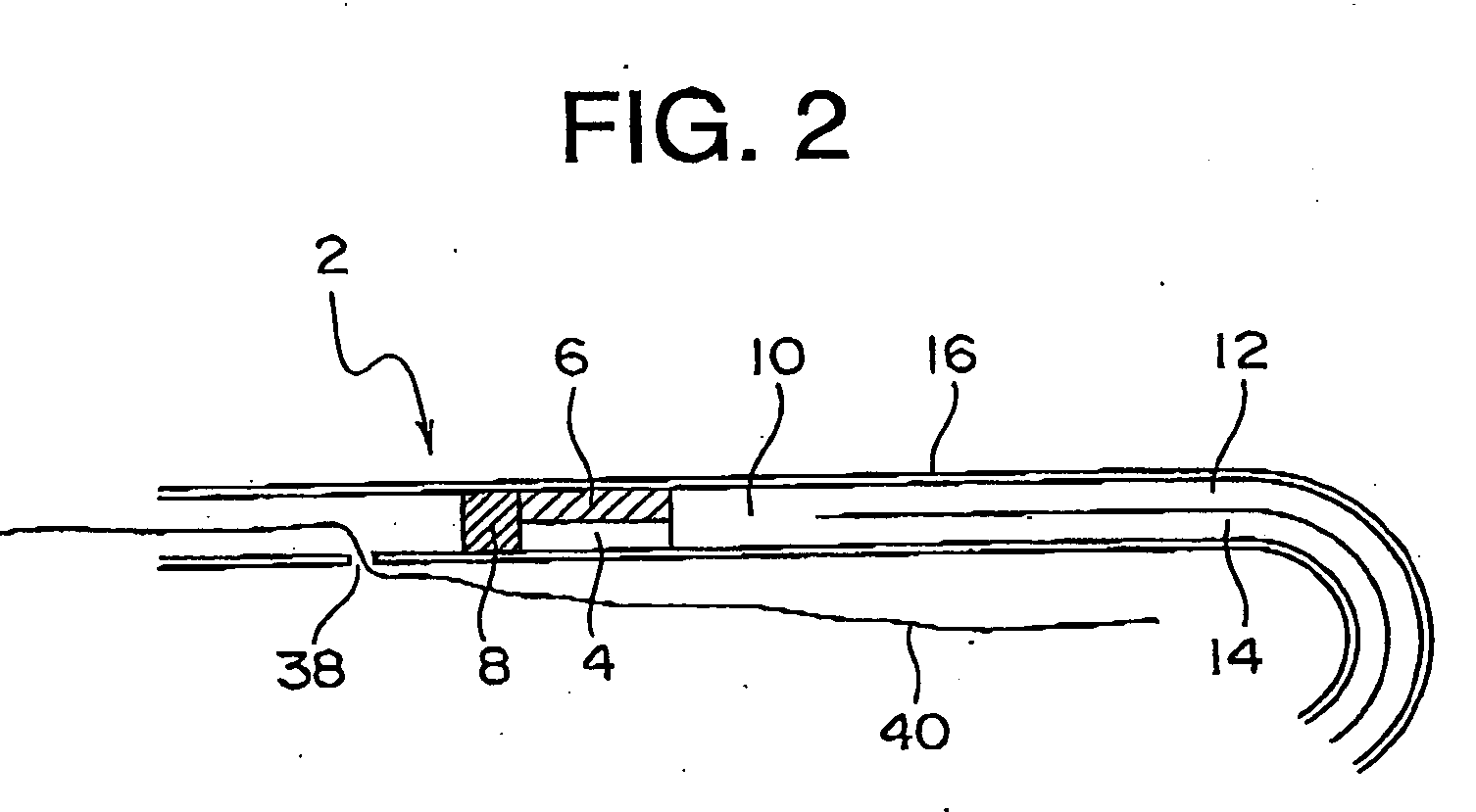
A sensitivity test was performed on the radiation detector shown in FIG. 1 to FIG. 3. In this case, the scintillator was made of plastic with the diameter of 1.0 mm and the length of 5.0 mm. The optical fiber aggregation was prepared by bundling up some tens of optical fibers with the diameter of 40 μm to be in the diameter of 0.8 mm and the length of 2000 mm. The scintillator and the optical fibers were not covered by a lightproof cover so that the test was carried out in a dark field. The test results performed on 111In as gamma-ray nuclide and 89Sr as beta-ray nuclide are as follows.

1. Detection Efficiency, Detection Limit

After dropping 3.0 μl radiation source into a dent with the diameter of 2.0 mm and the depth of 1.3 mm formed in an acryl plate, the dent was sealed and the scintillator was set to be in contact with the radiation source sealed area for carrying out the measurement. A set of measurement for 10 seconds was repeated for 10 times and the average was calculated...


PUM


Abstract

The present invention provides a radiation detector capable of detecting the radioactive substance accumulated in the tissue inside a body by inserting a detection unit into blood vessels. In the radiation detector of the present invention, comprising a detection unit (2) having a bar-type scintillator (4) which emits light by an incidence of radiation so as to transmit the light from the scintillator through an optical fiber, the detection unit is formed in a size capable of being inserted into the tubules while fine convexoconcaves are provided on the peripheral surface of the scintillator.

Description

TECHNICAL FIELD The present invention relates to a radiation detector for detecting radiation leakage in tubules and radiation substances present in tissues in the body system. More specifically, it relates to a radiation detector for detecting radiation substances accumulated in the tissues in the body system by inserting a detection unit into a blood vessel of coronary artery and the like after administering a radiopharmaceutical into the body system. BACKGROUND ART In the followings, the present invention will be described by referring mostly to its application inside blood vessels. Heart diseases among Japanese has been increasing year after year and it has now grown to be in the second place for the cause of death. Especially, unstable angina pectoris, acute myocardialinfarction, and inschemic heart sudden death are called as acute coronary syndromes, which are very serious diseases. Most of acute coronary syndromes are caused by thrombus formation triggered by a rupture of p...

Claims


Application Information

Patent Timeline
Patent Type & Authority Applications(United States)
IPC IPC(8): G01T1/00G01T1/161G01T1/169G01T1/20
CPCA61B6/4258G01T1/161A61B6/00
Inventor MOTOMURA, HIROSHISAITO, KAZUHIRO
Owner NIHON MEDI PHYSICS CO LTD
Why Eureka
Try Eureka