Eureka AIR delivers breakthrough ideas for toughest innovation challenges, trusted by R&D personnel around the world.

Multi-reflective acoustic wave device

Inactive Publication Date: 2005-01-20
VECTRON INT INC
View PDF6 Cites 22 Cited by
  • Summary
  • Abstract
  • Description
  • Claims
  • Application Information

AI Technical Summary

Benefits of technology

At the root of the present invention is the use of a plurality of local reflections in a predetermined and novel manner, to obtain the narrow bandwidth, high efficiency device that can tolerate damping effects while maintaining a usable Q factor and insertion loss, and thus provides a sensor with desirable characteristics. Thus in simplified general terms, the preferred embodiment of the invention provides for a long input transducer and a long output transducer, both having electromechanically signi

Problems solved by technology

However, as the operating frequency increases, creating mechanically insignificant electrodes becomes harder as the dimensions decrease inversely to the frequency.
Furthermore, in piezoelectric materials such as lithium niobate having high piezoelectric coupling, mechanically insignificant electrodes are electrically (and thus electromechanically) significant.
However a method of connecting more than one consecutive electrode to the same polarity is known to locally cancel the resulting electromechanical reflections and thus make the electrodes effectively be electromechanically insignificant, even at higher frequencies or in high coupling materials.
Therefore, exposing a driven piezoelectric crystal to contact with a fluid or a polymer material will dampen the wave propagation in the crystal, and change the characteristic response of the device.
However, as the transducers and their respective circuits are not ideal, the current produced in the output transducer, unless delivered to a short-circuit load, will cause regeneration of the input signal, which will cause a regeneration of the signal at the input transducer, and so forth ad infinitum.
This reflective phenomenon hinders the design of devices such as acoustic wave delay lines, while other devices such as resonators, take advantage of it.
Large number of electrodes or the use of electromechanically significant electrodes, causes triple transit echoes, and also another problem considered undesirable by those skilled in the art, (see Matthews page 156, line 3) of “- - - reflections within a given transducer - - - ”.
The phase coherent delay line using bi-directional transducers suffers from low efficiency, which limits the availability of dynamic range needed for sensor applications.
The unidirectional transducers are dependent on a critical balance of mechanical reflections and electrical regeneration, which is difficult to maintain over the variations in electrical parameters and insertion loss dynamic range needed for sensor applications.
This is, in part, a result of the variable mechanical damping involved, which alters both the required point of balance between reflection and regeneration and the amount of reflection available to balance the regeneration.
However, when dampening is applied to the conventional resonator, such as by exposing it to a liquid, or depositing a film thereupon, the signal decays rapidly, before it can be reflected back into the transducers a sufficient number of times. Dampening therefore turns the high Q factor resonator in free air, into a very low Q factor device when coated or suspended in other fluids.
Because a resonator degrades very rapidly upon dampening from external effects, it is of limited use in sensor applications having substantial damping of acoustic waves.
Additionally, loading a resonator by the like of a polymer film, significantly raises the resonator's typically low insertion loss, often increasing from approximately 7 dB to approximately 20 dB with even light damping.
Clearly this causes a reduction in the dynamic range available for a sensor application.

Method used


Image

  • Multi-reflective acoustic wave device
  • Multi-reflective acoustic wave device
  • Multi-reflective acoustic wave device

Examples


Embodiment Construction

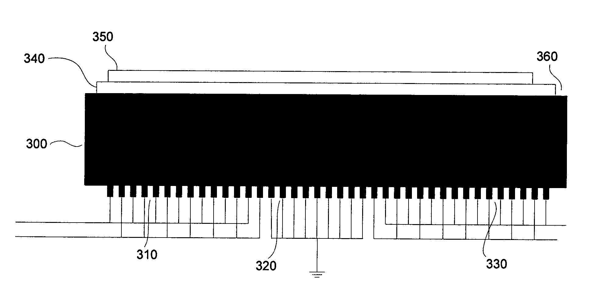
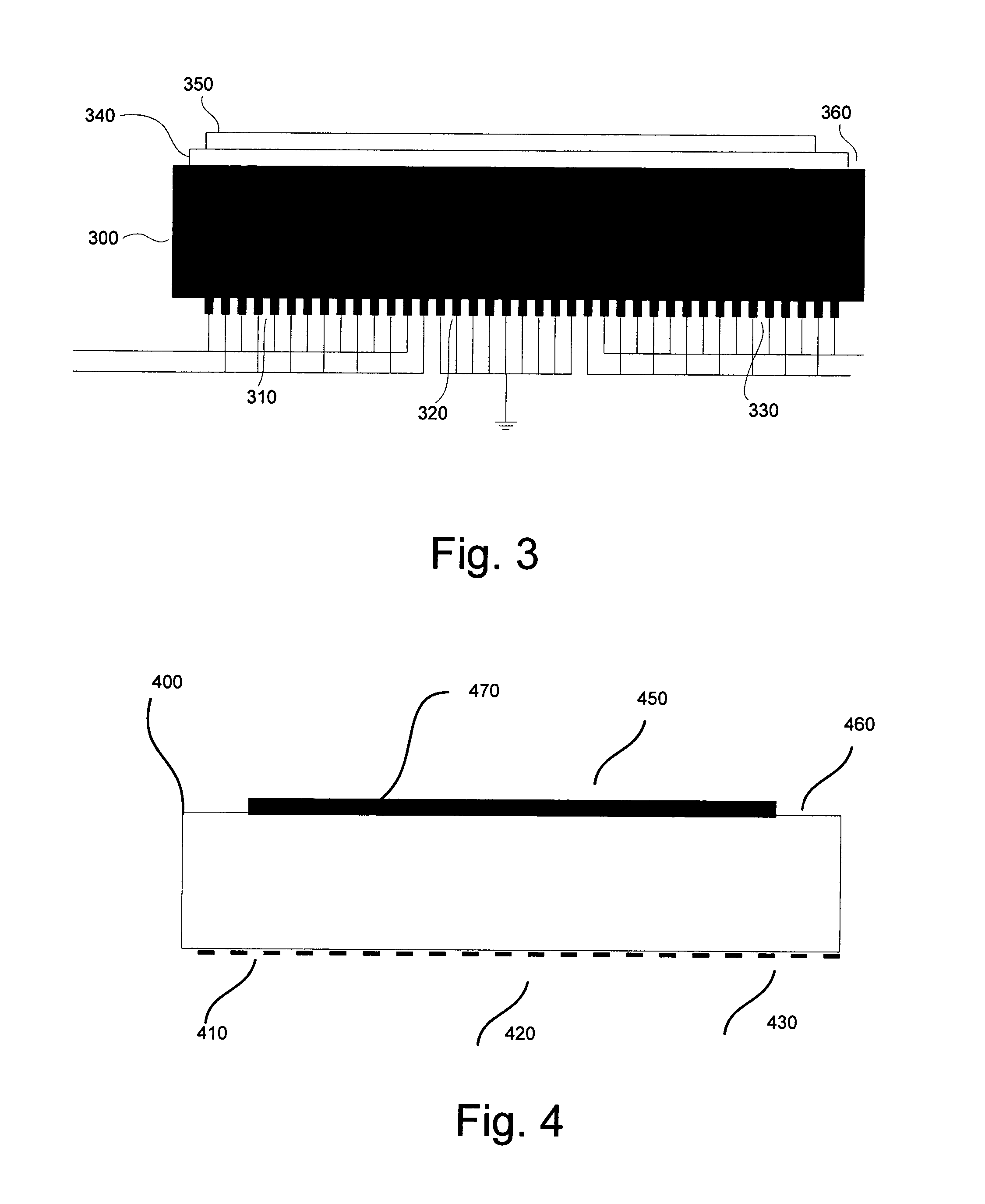
Reference is now made to FIG. 3 to provide a description of the preferred embodiment of the present invention, which comprises a structure having a substrate 035 which may be constructed of several layers, or be made of uniform material. At least one layer of the substrate, or all of it, is made of piezoelectric substance having essentially uniform thickness. The piezoelectric substance has at least one substantially flat surface, constructed to guide an acoustic wave. The preferred flat surface is one polished to a flatness having variations that are insignificant compared to the intended wavelength.

A large reflective grating (310, 320 and 330) is deposited on the flat surface. It is substantially periodic within a certain tolerance of the intended wavelength, so that it will continue propogation of an acoustic wave while remaining synchronous with the wave. While the reflective grating is essentially periodic and preferably coherent, it may contain areas without gratings, or ot...


PUM


Abstract

An acoustic wave device, which utilizes multiple localized reflections of acoustic wave for achieving an infinite impulse response while maintaining high tolerance for dampening effects, is disclosed. The device utilized a plurality of electromechanically significant electrodes disposed on most of the active surface. A plurality of sensors utilizing the disclosed acoustic wave mode device are also described.

Description

FIELD OF THE INVENTION This application is directed generally to acoustic wave devices, and more particularly to a piezoelectric device allowing operation through large variations of temperatures and perturbation dampening. BACKGROUND OF THE INVENTION Acoustic wave devices have been used extensively in the art as frequency reference resonators, delay lines, and sensors. The oldest acoustic wave device structure is the parallel plate resonator, which consists of a plate of piezoelectric material having substantially flat and parallel polished surfaces, one or both of which support one or more conducting electrodes. When a voltage signal is applied between the electrodes, stress fields induce elastic deformations of the crystal (strain fields). The deformations of the crystal alter the distribution of charge within the crystal and a net flow of charge (a current) exists. A more advanced acoustic wave device utilizes surface acoustic waves, surface transverse waves, or acoustic plat...

Claims


Application Information

Patent Timeline
IPC IPC(8): G01N29/032G01N29/24H01L41/08H03HH03H9/02H03H9/25H03H9/64
CPCG01N29/2437H03H9/42G01N2291/0422G01N29/2462H03H9/25
Inventor ANDLE, JEFFREY C.
Owner VECTRON INT INC
Why Eureka
Eureka Blog
Learn More