Polarizing, photochromic devices and methods of making the same

a technology of photochromic devices and polarizing elements, applied in the field of optical elements and security liquid crystal cells, can solve the problems of not being able to achieve the net linear polarization of transmitted radiation, not being able to store or display information, and not being well suited to use under certain low-light conditions

Active Publication Date: 2005-01-20
TRANSITIONS OPTICAL INC
View PDF98 Cites 233 Cited by
  • Summary
  • Abstract
  • Description
  • Claims
  • Application Information

AI Technical Summary

Benefits of technology

Other non-limiting embodiments relate to security elements. For example, one non-limiting embodiment provides a security element connected to at least a portion of a substrate, the security element comprising an at least partial coating having a first state and a second state connected to at least a portion of the substrate, the at least partial coating being adapted to switch from a first state to a second state in response to at least actinic radiation, to re...

Problems solved by technology

Thus, while conventional linearly polarizing elements are useful in reducing reflected light glare, because of their tint, they are not well suited for use under certain low-light conditions.
Further, because conventional linearly polarizing elements have only a single, tinted linearly polarizing state, they are limited in their ability to store or display information.
Thus, while dichroic materials are capable of preferentially absorbing one of two orthogonal plane polarized components of transmitted radiation, if the molecules of the dichroic material are not suitably positioned or arranged, no net linear polarization of transmit...

Method used


Image

  • Polarizing, photochromic devices and methods of making the same
  • Polarizing, photochromic devices and methods of making the same
  • Polarizing, photochromic devices and methods of making the same

Examples


example 1

Sample substrates having a coating comprising an aligned anisotropic material and a photochromic-dichroic compound that was at least partially aligned in the activated state connected thereto were prepared as follows. A comparative substrate having a coating comprising an aligned anisotropic material and a commercially available photochromic dye that was at least partially aligned in the activated state connected thereto was also prepared as follows.

Part A: Preparation of Solutions of Anisotropic Materials

Each of the liquid crystal monomers listed in Table I were added to a beaker in the order listed with stirring:

TABLE ILiquid CrystalMonomerAmount (g)RM 2313.25RM 25723.25RM 8233.25RM 10543.25

1RM 23 is a liquid crystal monomer (LCM) available from EMD Chemicals, Inc and is reported to have the molecular formula of C23H23NO5.

2RM 257 is a liquid crystal monomer (LCM) available from EMD Chemicals, Inc and is reported to have the molecular formula of C33H32O10

3RM 82 is a liquid ...

example 2

Ophthalmic substrates having an at least partial coating were prepared using an overmold process as described below.

Step 1

The procedure of Parts A & C of Example 1 were followed to form an overmolding coating composition, except that the essentially all of the solvent in the coating composition was removed by sparging with air for 2 hours prior to adding about 2 weight percent of P / D-3, on a total weight basis, to produce the overmolding coating composition.

Step 2

A six-base lens prepared from CR-39® monomer was cleaned following the procedure of Part D, Step 1 of Example 1 except that the lens was dried in an oven at 100° C. for 10 minutes prior to treatment with oxygen plasma.

Step 3

The procedure of Part D, Step 2 of Example 1 was followed to form an orientation facility comprising a coating of an at least partially ordered photo-orientable polymer network to the lens and a glass mold, except that a 90 second exposure to the linearly polarized ultraviolet light was used...

example 3

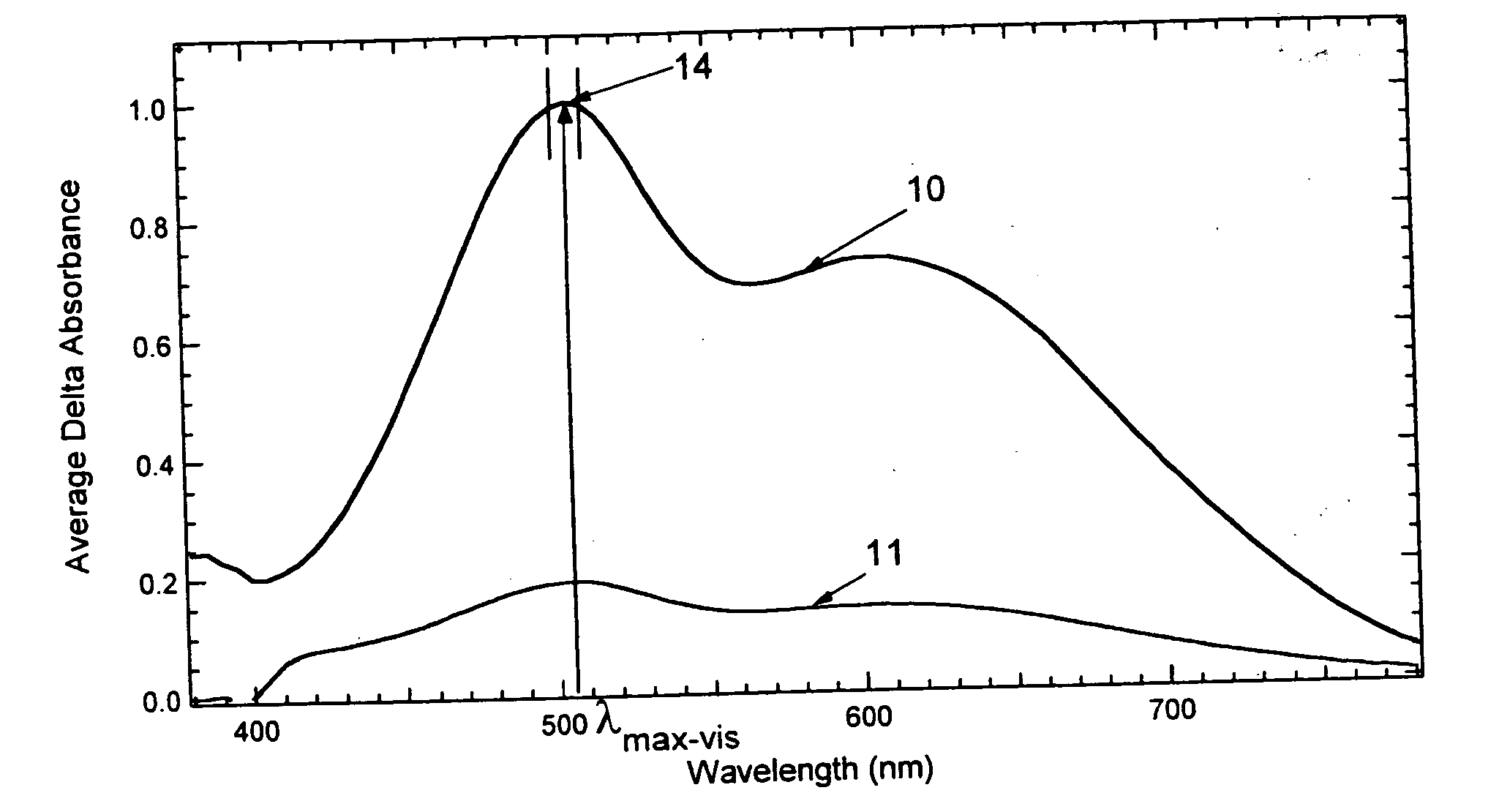
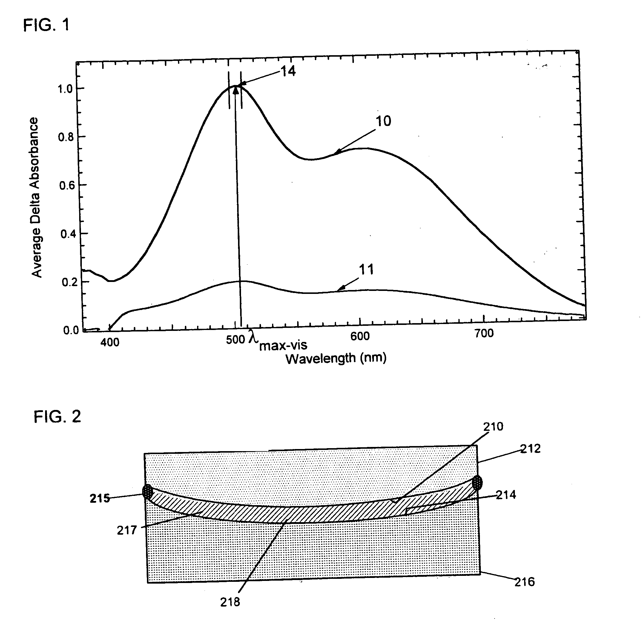
An optical bench was used to measure the average absorption ratios for each of the coated samples prepared in Examples 1 and 2 above as follows. Each of the coated samples was placed on the optical bench with an activating light source (an Oriel Model 66011 300-Watt Xenon arc lamp fitted with a Melles Griot 04 IES 211 high-speed computer controlled shutter that momentarily closed during data collection so that stray light would not interfere with the data collection process, a Schott 3 mm KG-2 band-pass filter, which removed short wavelength radiation, neutral density filter(s) for intensity attenuation and a condensing lens for beam collimation) positioned at a 30° angle of incidence to the surface of the coated substrate.

A broadband light source for monitoring response measurements was positioned in a perpendicular manner to the surface of the coated substrate. Increased signal of shorter visible wavelengths was obtained by collecting and combining separately filtered light fro...


PUM


Abstract

Various embodiments disclosed herein relate to optical elements comprising an at least partial coating having a first state and a second state connected to at least a portion of a substrate, the at least partial coating being adapted to switch from the first state to the second state in response to at least actinic radiation, to revert back to the first state in response to thermal energy, and to linearly polarize at least transmitted radiation in at least one of the first state and the second state. Other embodiments relate to optical elements comprising a substrate and at least one at least partially aligned photochromic-dichroic compound connected to at least a portion of the substrate and having an average absorption ratio greater than 2.3 in the activated state as determined according to CELL METHOD. Still other embodiments relate to security devices, liquid crystal cells and methods of making the same.

Description

STATEMENT REGARDING FEDERALLY SPONSORED RESEARCH OR DEVELOPMENT Not applicable. Reference to a Sequence Listing Not applicable. BACKGROUND Various embodiments disclosed herein relate generally to optical elements, security liquid crystal cells and methods of making the same. Conventional, linearly polarizing elements, such as linearly polarizing lenses for sunglasses and linearly polarizing filters, are typically formed from stretched polymer sheets containing a dichroic material, such as a dichroic dye. Consequently, conventional linearly polarizing elements are static elements having a single, linearly polarizing state. Accordingly, when a conventional linearly polarizing element is exposed to either randomly polarized radiation or reflected radiation of the appropriate wavelength, some percentage of the radiation transmitted through the element will be linearly polarized. As used herein the term “linearly polarize” means to confine the vibrations of the electric vector of lig...

Claims


Application Information

Patent Timeline
IPC IPC(8): G02B5/23G02B5/30G02B27/28G02F1/1335
CPCC07D311/94C07D405/10C07D405/14C07D498/10C09B57/00Y10T428/24934G02B5/23G02B5/3016G02B5/3025G02F1/1335G03C1/73C09K19/60
Inventor KUMAR, ANILFOLLER, PETER C.BLACKBURN, FORREST R.SHAO, JIPINGHE, MENGKELLAR, TERRY A. II
Owner TRANSITIONS OPTICAL INC
Why Eureka
Try Eureka