
Optical film, polarizing optical film, and image viewing display

Active Publication Date: 2005-01-27
NITTO DENKO CORP
View PDF6 Cites 22 Cited by
  • Summary
  • Abstract
  • Description
  • Claims
  • Application Information

AI Technical Summary

Benefits of technology

The present invention aims at providing optical film having characteristics of giving wide viewing angle, and also outstanding durability.
An optical film of the present invention uses polymer films including styrene resins in addition to polycarbonate resins. Blending of the styrene resins enables control of a photoelastic coefficient of the optical films within a range of 2.0×10⁻¹¹ to 6.0×10⁻¹¹ m2 / N, realizing outstanding durability. Therefore, application of the optical film of the present invention for large-sized panels reduces change of retardation value under stress-applied conditions, enabling suitable use in application wherein, for example, high heat resistance, and high temperature and high moisture resistance are required. Photoelastic coefficient is preferably in a range of 3.0×10⁻¹¹ to 5.0×10⁻¹¹ m2 / N. When the photoelastic coefficient exceeds 6.0×10⁻¹¹ m2 / N, durability may not fully be exhibited and retardation change is not small under stress-applied conditions. On the other hand, when the photoelastic coefficient is less than 2.0×10⁻¹¹ m2 / N, inferior stretching processability is provided and control of Nz coefficient disadvantageously becomes difficult. Moreover, since the optical film has polycarbonate resins as a principal component, it has excellent expression of birefringence and controllability based on polycarbonate resins. Moreover, polycarbonate resins and styrene resins have excellent compatibility with each other, which gives high transparency of the optical film.
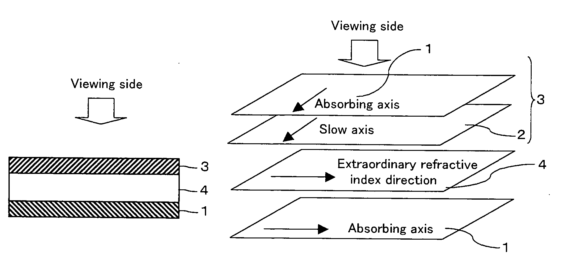
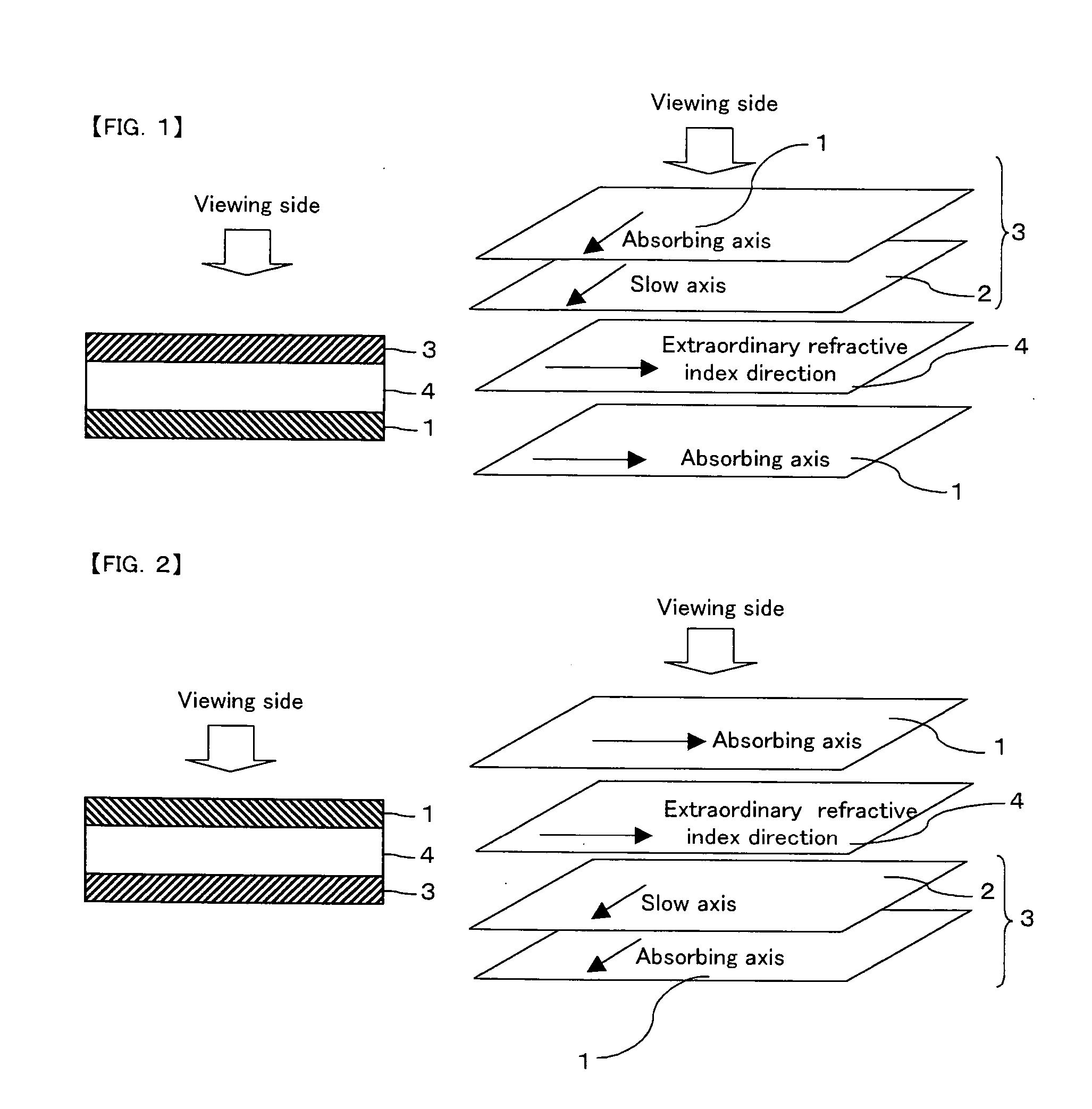
The optical film (for example, retardation film) of the present invention may be used for a polarizing optical film in a state laminated with a polarizing plate. A polarizing optical film wherein the optical film is laminated with a polarizing plate so that a slow axis of the optical film and an absorbing axis of the polarizing plate may be parallel to each other, or so that they may be perpendicular to each other, can compensate a shift of geometric optical axis of the polarizing plate caused when observed in a oblique direction, and, as a result, can provide a wide viewing angle.
The optical film and polarizing optical film may be used for various kinds of image viewing displays, and liquid crystal displays in IPS mode are suitable as the image viewing displays. Disposing of the polarizing optical film on either one surface of liquid crystal cells in IPS mode can reduce leakage of light that has been caused in liquid crystal displays of IPS mode in black display. This type of liquid crystal displays in IPS mode has a high contrast ratio over all directions, and can realize easily viewable display having a wide viewing angle.

Problems solved by technology

However, optical films obtained by stretching of polycarbonate resin films have a large birefringence change when stress is applied; that is, they have a large photoelastic coefficient.
Therefore, there occurs a problem that the optical films easily cause a large degree of unevenness when they are adhered to polarizing plates.
Moreover, in recent years, upsizing of liquid crystal panels, such as in liquid crystal televisions, increases stress that works on panels, and therefore optical film materials having smaller change of retardation (change of birefringence) is increasingly required.
Moreover, the optical films have such problems that exhibit large retardation variation, under use environment after adhered onto viewing displays.
Since they had this problem, the optical films were not suitable for application in recent years wherein high heat resistance, and high temperature and high moisture resistance were required.
However, although the norbornene resins have a small photoelastic coefficient, they simultaneously show a characteristic to have a small birefringence, providing a limitation to retardation given by stretching process.
Especially, control of three dimensional refractive index satisfying a relationship of Nz coefficient≦0.9 is difficult.
However, in TN mode, even if black display is required, optical leakage resulting from birefringence caused by liquid crystal molecules near a substrate made it difficult to realize perfect display of black color owing to driving characteristics thereof.
Although almost perfect black display may be realized in normal direction to a panel in IPS mode, when a panel is observed in a direction shifted from normal direction, inevitable optical leakage occurs caused by characteristics of a polarizing plate in a direction shifted from an optical axis of the polarizing plates disposed on upper and lower sides of the liquid crystal cell, as a result, causing to a problem of narrowing of a viewing angle.
However, retardation films conventionally known have not been able to easily realize sufficient wide viewing angles.

Method used


Image

  • Optical film, polarizing optical film, and image viewing display
  • Optical film, polarizing optical film, and image viewing display
  • Optical film, polarizing optical film, and image viewing display

Examples


example 1

(Polymer Film)

As a polymer film including a polycarbonate resin and a styrene resin, PF film (thickness of 55 μm): a product name, manufactured by Kaneka Corp. was used. The polycarbonate resin includes a polymer originated in 2,2-bis(4-hydroxy phenyl)propane, and 1,1-bis(4-hydroxy phenyl)-3,3,5-trimethyl cyclohexane with a blending ratio of 40:60 (by weight ratio). Moreover, a content ratio of a styrene resin (weight average molecular weight 10,000) in the polymer film was 20% by weight.

(Optical Film)

Heat-shrinkable films, which are a biaxially stretched polyester film, were adhered on both sides of the polymer film (PF film) through pressure sensitive adhesive layers. Then, the obtained film was held with a simultaneous biaxial stretching machine, and stretched 1.3 times at 145° C. The obtained stretched film was transparent, and had a thickness of 60 μm, a front retardation of 140 nm, a thickness direction retardation of 70 nm, and an Nz coefficient of 0.5. Moreover, a pho...

example 2

(Optical Film)

Heat-shrinkable films, which are a biaxially stretched polyester film, were adhered on both sides of a polymer film (PF film) used in Example 1 through pressure sensitive adhesive layers. Then, the obtained film was held with a simultaneous biaxial stretching machine, and was stretched 1.1 times at 146° C. The obtained stretched film was transparent, and had a thickness of 61 μm, a front retardation of 130 nm, a thickness direction retardation of 39 nm, and an Nz coefficient of 0.3. Moreover, a photoelastic coefficient gave 5.0×10⁻¹¹, and Tg 140° C.


PUM

PropertyMeasurementUnit
Glass transition temperatureaaaaaaaaaa
Molecular weightaaaaaaaaaa
Refractive indexaaaaaaaaaa

Abstract

An optical film obtained by stretching a polymer film comprising a polycarbonate resin and a styrene resin: wherein a photoelastic coefficient is 2.0×10⁻¹¹ to 6.0×10⁻¹¹ m2 / N, and a three dimensional refractive index is controlled so that an Nz coefficient may satisfy a relationship of Nz≦0.9 and a front retardation (Re) may satisfy a relationship of Re≧80 nm, has characteristics of giving wide viewing angle and also outstanding durability.

Description

BACKGROUND OF THE INVENTION 1. Field of the Invention The present invention relates to an optical film. An optical film of the present invention may be used independently or may be used in combination with other optical films as various optical films, such as retardation films, viewing angle compensation films, optical compensation films, elliptically polarizing plates, and brightness enhancement films. An optical film of the present invention is especially useful when it is laminated with polarizing plates to be used as elliptically polarizing plates. In addition, the present invention relates to an image viewing display such as a liquid crystal display, an organic EL (electroluminescence) viewing display, a PDP using the optical film, and the elliptically polarizing plate. Especially, the optical film, and polarizing optical film of the present invention may be suitably used for liquid crystal displays that can be mounted in portable information and telecommunications instrumen...

Claims


Application Information

Patent Timeline
IPC IPC(8): C08L25/04C08L69/00G02B5/30G02F1/1335G02F1/13363
CPCG02B5/3083Y10T428/1036G02F1/133634C09K2323/03B32B27/36C08J5/18C08J2325/00C08J2369/00
Inventor HATA, MASAHIROKINOSHITA, RYOUJIYANO, SHUUJIKAWAI, MASAYUKI
Owner NITTO DENKO CORP
Features
  • Generate Ideas
  • Intellectual Property
  • Life Sciences
  • Materials
  • Tech Scout
  • Unparalleled Data Quality
  • Higher Quality Content
  • 60% Fewer Hallucinations
Learn More