Optically-assisted magnetic recording head and optically-assisted magnetic recording apparatus

a technology of magnetic recording apparatus and magnetic recording head, which is applied in the field of optically assisted magnetic recording apparatus, can solve the problems of difficult to ensure thermal agitation resistance, troublesome operation, and inability to record, etc., and achieves stable magnetic recording, high efficiency, and ultra-high density

Inactive Publication Date: 2005-01-27
KK TOSHIBA
View PDF8 Cites 31 Cited by
  • Summary
  • Abstract
  • Description
  • Claims
  • Application Information

AI Technical Summary

Benefits of technology

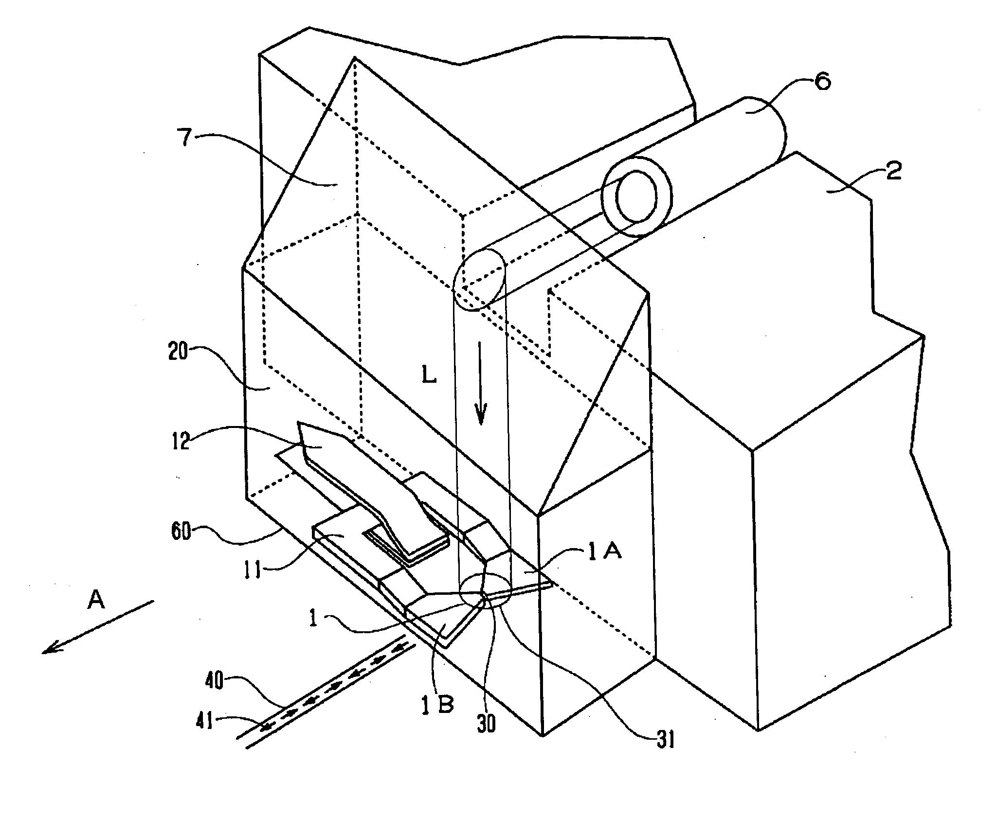
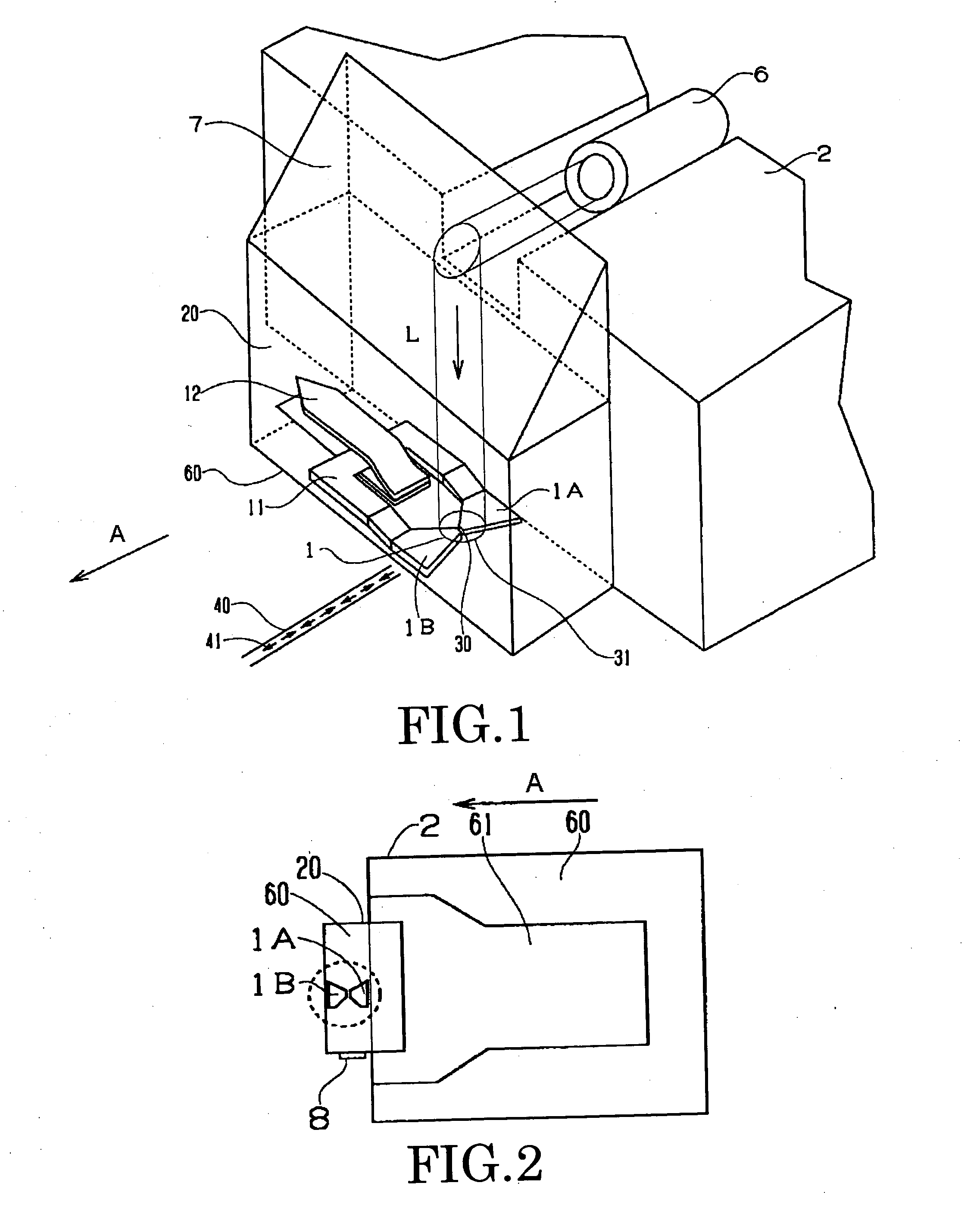
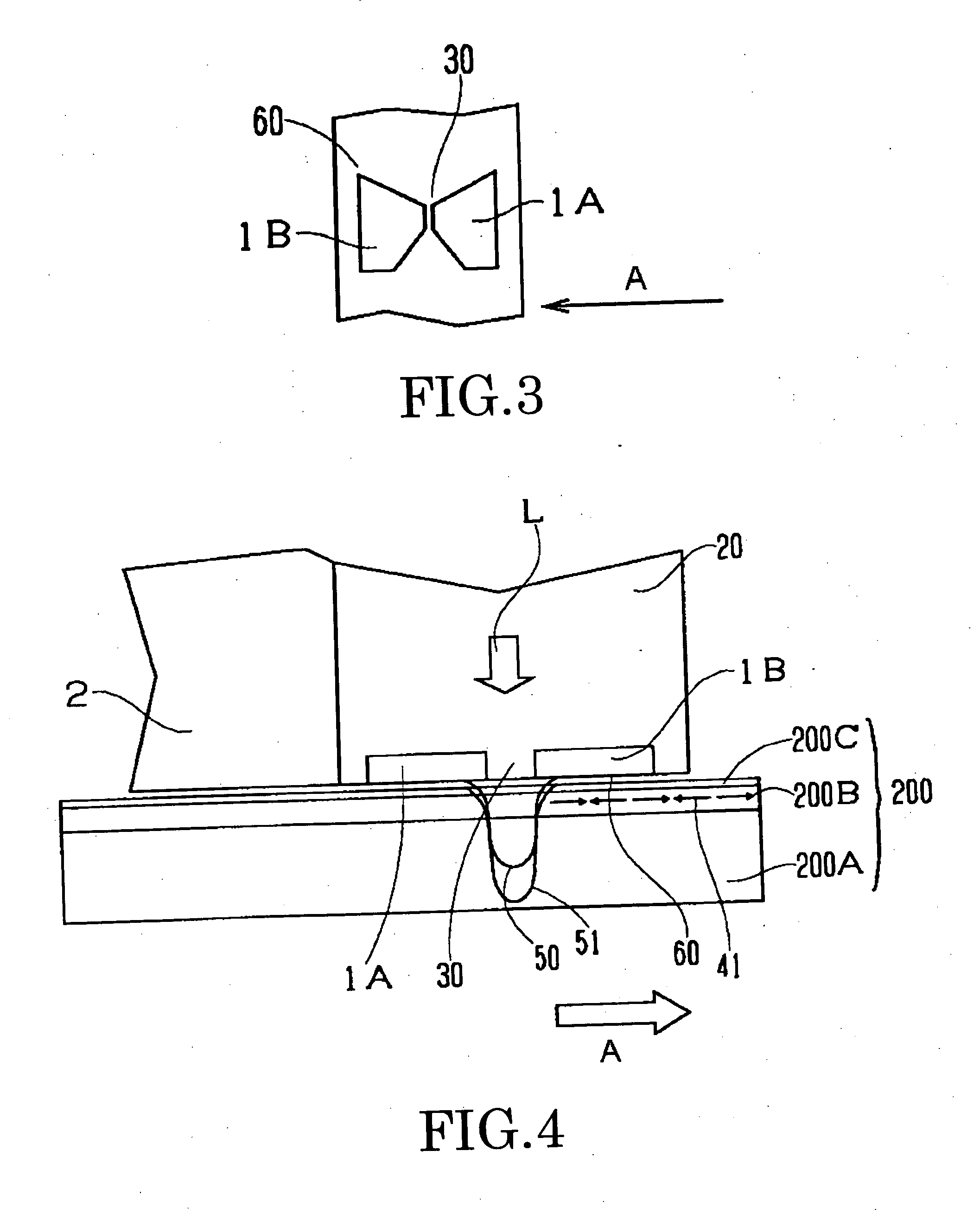
[0028] That is, the use of the yokes having a gap as a bowtie type evanescent light probe and simultaneously as a magnetic pole for magnetic writing enables optically-assisted stable magnetic recording of an ultra-high density.

Problems solved by technology

Recently, however, it has become apparent that the thermal agitation of the medium disturbs the higher density of HDD.
When V is made smaller for a lower medium noise, KuV becomes smaller with a result that the thermal energy near the room temperature will disturb information written in the medium, and reveals the problem of thermal agitation.
According to the analysis made by Sharrock et al., if the ratio between magnetic energy and thermal energy (kT, where k is Boltzman's constant and T is absolute temperature) of a particle, KuV / kT, is not 100 or so, it will impair the reliability of the record life.
If reduction of the particle size is progressed for a lower medium noise with the anisotropy energy density Ku being maintained at (2to 3)×106 erg / cc of the CoCr group alloy conventionally used as a magnetic film in the recording medium, it is getting difficult to ensure a thermal agitation resistance.
However, simply increasing the Ku value for compatibility between the small particle size and thermal agitation resistance will lead to another problem.
The problem concerns the recording sensitivity.
In this case, however, since the magnetic field intensity necessary for recording to the medium at a temperature approximate to the room temperature is over 10 kOe, recording to the medium is disabled.
Therefore, if the Ku value of the medium is simply increased, there will arise the problem of the recording to the medium being impossible.
In a medium having such a large Ku value, since the magnetic field intensity necessary for recording exceeds the intensity of a magnetic field developed by the recording head near a room temperature, recording is not possible.
However, volume V of the magnetic particles can be regarded infinite, the problem of thermal agitation is out of problem.
Since this related art uses far-field light beams as the heat source for heating a medium and locating a recording pole and the beam source in confrontation with the medium, double-side recording is impossible and an evanescent light cannot be used.
That is, even when combining a short-wavelength laser and a high NA lens, the limit of the track width is hundreds of nm, therefore, a higher recording density is hard to realize.
Moreover, since the precise alignment of the light-irradiated position and the recording field applying position is quite difficult in that related art, a higher recording density is hard to realize.
As explained above, the use of a multiparticle medium in an optically-assisted magnetic recording system involves various problems, namely, uncertainty of double-side recording, difficulty of employing an evanescent light, difficulty of realizing a precise alignment of the irradiating position and magnetic field applying position, difficulty of realization of a compact, light and inexpensive optically-assisted magnetic recording head, and particularly in a mode using an evanescent light

Method used


Image

  • Optically-assisted magnetic recording head and optically-assisted magnetic recording apparatus
  • Optically-assisted magnetic recording head and optically-assisted magnetic recording apparatus
  • Optically-assisted magnetic recording head and optically-assisted magnetic recording apparatus

Examples


third embodiment

[0143]FIG. 18B is a plan view of the recording head as the third embodiment, taken from its medium-facing surface. Here again, common or equivalent elements or components to those already explained with reference to FIGS. 1 through 17 are labeled with common reference numerals, and their detailed explanation is omitted.

[0144] In this example, a laser element 80A is provided as the light source of the light beam on the head slider 2. The laser element 80A is a surface emission type light-emitting element such as vertical cavity surface-emitting laser (VCSEL). The light beam L emitted from the emission surface of the laser element 80A is irradiated onto the gap 30 of the recording element 1 via an optical means 90 such as a lens, if necessary.

[0145] The specific example shown here makes it possible to integrate the laser element as the light source, the recording element 1 and also the magnetic recording element, not shown, inside the head slider 2.

[0146] For example, these componen...

fourth embodiment

[0149]FIG. 19B is a plan view of the recording head as the fourth embodiment, taken from its medium-facing surface. Here again, common or equivalent elements or components to those already explained with reference to FIGS. 1 through 18B are labeled with common reference numerals, and their detailed explanation is omitted.

[0150] The head according to this specific example is similar in construction to the third specific example. However, here is used an edge-emitting type laser element 80B. Even by using the edge-emitting type laser element 80B, highly efficient evanescent light can be easily generated.

[0151] Although explanation has been omitted from the description about the foregoing specific examples with reference to FIGS. 1 through 19B, from the viewpoint of preventing mutual abrasion and crushing of the magnetic recording medium 200 and the head slider 2, which may occur while the head slider 2 moves relative to the magnetic recording medium 200, floating above or in contact ...


PUM

PropertyMeasurementUnit
anisotropy energy densityaaaaaaaaaa
particle sizeaaaaaaaaaa
thicknessaaaaaaaaaa

Abstract

A pair of members opposed to each other via a gap are commonly used as an evanescent light probe and a writing magnetic head. When the spacing and width of the gap are smaller than the wavelength λ of injected light, highly intensive evanescent light is generated from the gap position of the opposite surface. Magnetic writing is carried out by applying a recording magnetic field from the pair of members to a medium heated by the evanescent light.

Description

CROSS-REFERENCE TO RELATED APPLICATIONS [0001] This application is based upon and claims the benefit of priority from the prior Japanese Patent Application No. 2001-095518, filed on Mar. 29, 2001; the entire contents of which are incorporated herein by reference. BACKGROUND OF THE INVENTION [0002] The present invention relates to an optically-assisted magnetic recording head and an optically-assisted magnetic recording apparatus, and more particularly, to a novel optically-assisted magnetic recording head and an optically-assisted magnetic recording apparatus, capable of heating a magnetic recording medium by a light irradiation in order to magnetically record data to the medium with an extremely high density. [0003] Magnetic recording apparatus for magnetically recording and reproducing information are under continuous development as large-capacity, high-speed and inexpensive information storage means. Especially, recent hard disc drive (HDD) has shown remarkable improvements. As p...

Claims


Application Information

Patent Timeline
Patent Type & Authority Applications(United States)
IPC IPC(8): G11B5/00G11B11/10G11B5/02G11B5/127G11B5/31G11B5/39G11B7/00G11B13/04
CPCG11B5/127G11B5/3103G11B5/3967G11B5/4826G11B2005/0021G11B7/00G11B13/045G11B2005/0002G11B2005/0005G11B5/4833
Inventor AKIYAMA, JUNICHIKIKITSU, AKIRAKAI, TADASHINAGASE, TOSHIHIKOMAEDA, TOMOYUKI
Owner KK TOSHIBA
Why Eureka
Try Eureka