Light emitting diode
- Summary
- Abstract
- Description
- Claims
- Application Information
AI Technical Summary
Benefits of technology
Problems solved by technology
Method used
Image

Examples
embodiment 1
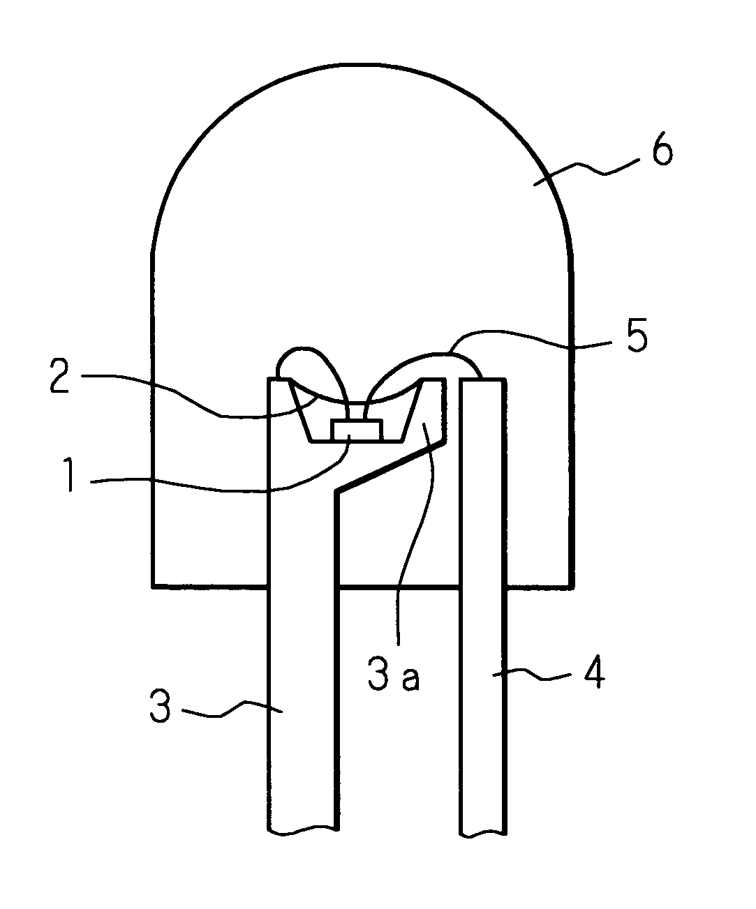
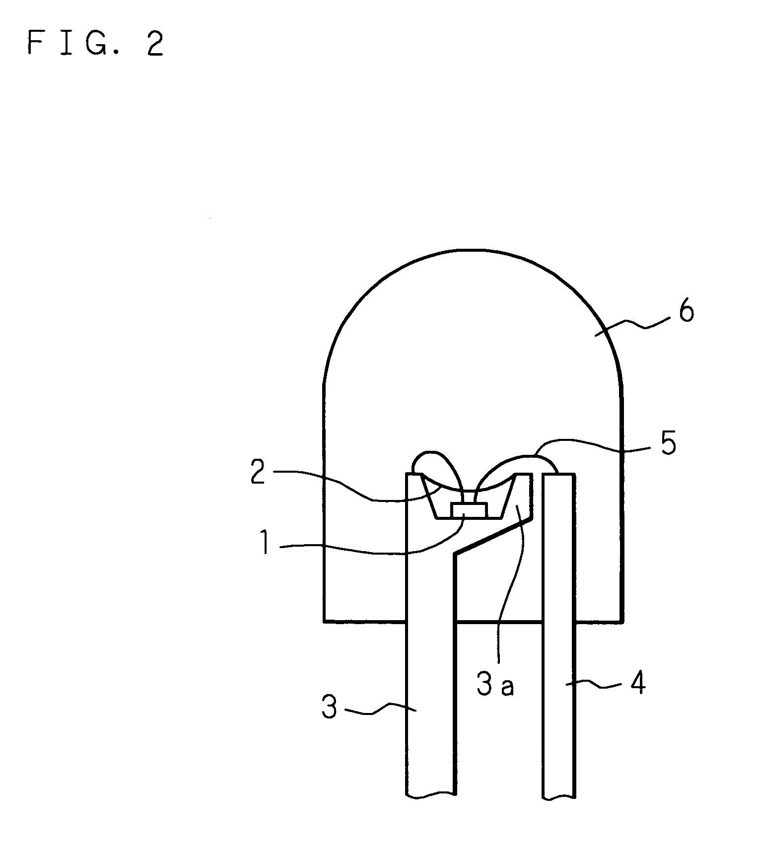
[0034]FIG. 2 is a front sectional view showing an LED of the present invention. The LED comprises lead frames 3 and 4, and the lead frame 3 has a recessed portion 3a in an end thereof. An LED element 1 constructed by stacking a plurality of semiconductor layers is adhered and fixed on the bottom of the recessed portion 3a by die-bonding. One of the electrodes of the LED element 1 is wire-bonded to the lead frame 3 by a metal wire 5, and the other electrode is wire-bonded to the lead frame 4 by a metal wire 5. The recessed portion 3a is filled with glass according to the present invention at a position closer to the bottom than a plane formed by the brim of the recessed portion 3a, so that a cover 2 covering the LED element 1 is formed. The end of the lead frame 3 where the cover 2 is formed and the end of the lead frame 4 are stored in a mold 6 made of an epoxy resin and having a top functioning as a convex lens.
[0035] The glass according to the present invention is low melting poi...
embodiment 2
[0047] Low melting point glass of Embodiment 2 that is glass according to the present invention has a composition composed of 90 mole % of C6H5SiO3 / 2 and 10 mole % of (CH3)2SiO. As the starting materials of the low melting point glass, PhTES and (CH3)2Si(OC2H5)2 (dimethyl diethoxy silane: hereinafter referred to as DMDES) are used.
[0048] A solution adjusted so that the mole ratio of PhTES, solution, water and acidic catalyst is 3:10:3:0.1 is produced, and then, when two to three hours have passed, a 0.1 M ethanol solution of DMDES is dropped into the solution to perform a hydrolysis polycondensation reaction with an open system in the air. Further, two or three hours later, aqueous ammonia is added (PhTES:ammonia=3:0.2) to the solution to completely hydrolyze the solution. Next, after completely gelling the solution at room temperature, the solution is heated at 70° C. for one day and at 110° C. for one day in an oven to remove the remaining ethanol and facilitate the polycondensat...
embodiment 3
[0053]FIG. 9 is a cross section showing an LED of Embodiment 3. In FIG. 9, numeral 7 represents a wiring board, and the LED of Embodiment 3 is a surface mount LED in which an LED element 1 is mounted on a surface of the wiring board 7. Electrodes 71 and 72 connectable to external devices are formed from both ends toward the surface of the wiring board 7 so that they are separated from each other, and the LED element 1 is mounted on the surface of one electrode 71 formed on the surface of the wiring board 7. One of the electrodes of the LED element 1 is wire-bonded to the electrode 71 by a metal wire 5, while the other electrode is wire-bonded to the electrode 72 on the surface of the wiring board 7 by a metal wire 5. A cover 2 is formed using low melting point glass similar to the low melting point glass of Embodiment 1 or Embodiment 2 on the periphery of the LED element 1, and the cover 2 covers the entire LED element 1 including a light emitting surface. Further, the cover 2, the ...
PUM
| Property | Measurement | Unit |
|---|---|---|
| Temperature | aaaaa | aaaaa |
| Temperature | aaaaa | aaaaa |
| Wavelength | aaaaa | aaaaa |
Abstract
Description
Claims
Application Information
 - R&D
- Intellectual Property
- Life Sciences
- Materials
- Tech Scout
- Unparalleled Data Quality
- Higher Quality Content
- 60% Fewer Hallucinations
Browse by: Latest US Patents, China's latest patents, Technical Efficacy Thesaurus, Application Domain, Technology Topic, Popular Technical Reports.
© 2025 PatSnap. All rights reserved.Legal|Privacy policy|Modern Slavery Act Transparency Statement|Sitemap|About US| Contact US: help@patsnap.com