Rotor structure of line-start permanent magnet synchronous motor
Inactive Publication Date: 2005-02-03
MARSTATE IND
View PDF8 Cites 18 Cited by
Summary
Abstract
Description
Claims
Application Information
AI Technical Summary
This helps you quickly interpret patents by identifying the three key elements:
Problems solved by technology
Method used
Benefits of technology
Benefits of technology
[0012] One of the objectives of the invention described in the first embodiment of the invention is to utilize the conventional LSPM synchronous motor of the hybrid type. This motor of the invention provides four fan-shaped magnetic poles having a central angle 90°. The circular arcs of the surfaces of the magnetic poles are defined as “the first eccentric circular arcs of the surface of the magnetic poles” having four “first eccentric points O1” as their centers that are offset from the rotor center O with offset lengths OS1 and radii R1. If the radius of the rotor is R, then R−R1=OS1. In this way, the air gap thickness of the motor constitutes a gradual and non-uniform distribution along the circumferences between the rotor and the stator. The length of the offset OS1 and the radius of curvature of the circular arc R1 can adjust to accommodate the variation of the range of the air gap thickness. The maximum air gap thickness T of the motor is anywhere from two to five times as much as the minimum air gap thickness t1, that is T=2t1˜5t1. In this way, the fact that the radial component of the magnetic flux density becomes very close to a sinusoidal wave distribution can further lower the cogging torque of the motor and reduce the operating vibration and noise of the motor. As the motor employs the first eccentric circular arcs of the surface of the magnetic poles, when the loading of the motor increases, even though the magnetic flux formed by the stator winding increases accordingly, the motor can still attenuate the effect of demagnetization of the magnetic field of the stator with respect to the permanent magnet. This is because that the air gap is relatively large at both ends of each of the fan-shaped magnetic poles.
[0014] One other objective of the invention described in the first embodiment of the invention is to provide a semi-circle recess at the mid-way of the first eccentric circular arcs of the surface of the magnetic poles. The diameter of the semi-circle recess is almost equal to the width of the tooth part of the stator of the motor. The recess can adequately attenuate the magnetic flux of the magnetic pole of the motor. In addition, the recess can also reduce the self-retaining torque caused by the magnetic flux of the magnetic pole of the motor so that the motor can improve its starting characteristic.
[0016] One further objective of the invention described in the third embodiment of the invention is to provide a smooth curve of “the second eccentric circular arcs of the surface of the magnetic pole” to substitute the above-mentioned semi-circle recesses. In this way, the motor can adequately reduce the radial component distribution of the magnetic flux density of the air gap at the mid-way of the second eccentric circular arcs of the surface of the magnetic poles. Moreover, the motor can further reduce the cogging torque as well as the vibration and noise during the operation. What is more, the LSPM synchronous motor can slightly attenuate the magnetic flux of the magnetic pole to reduce the transient state during the operation from stop to start due to the self-retaining torque caused by the fan-shaped magnetic pole of the motor. In this third embodiment, one can adjust the radius of the second eccentric circular arcs and the length of offset OS2 of the center of curvature O2 of the second eccentric circular arcs of the surface of the magnetic poles to accommodate the variation of the range of the air gap thickness. In this way, not only the motor can adequately reduce the self-retaining torque, but also the radial component of the magnetic flux density becomes very close to a sinusoidal wave distribution.
As a result, the motor is subject to occurrence of operating vibration and noise.
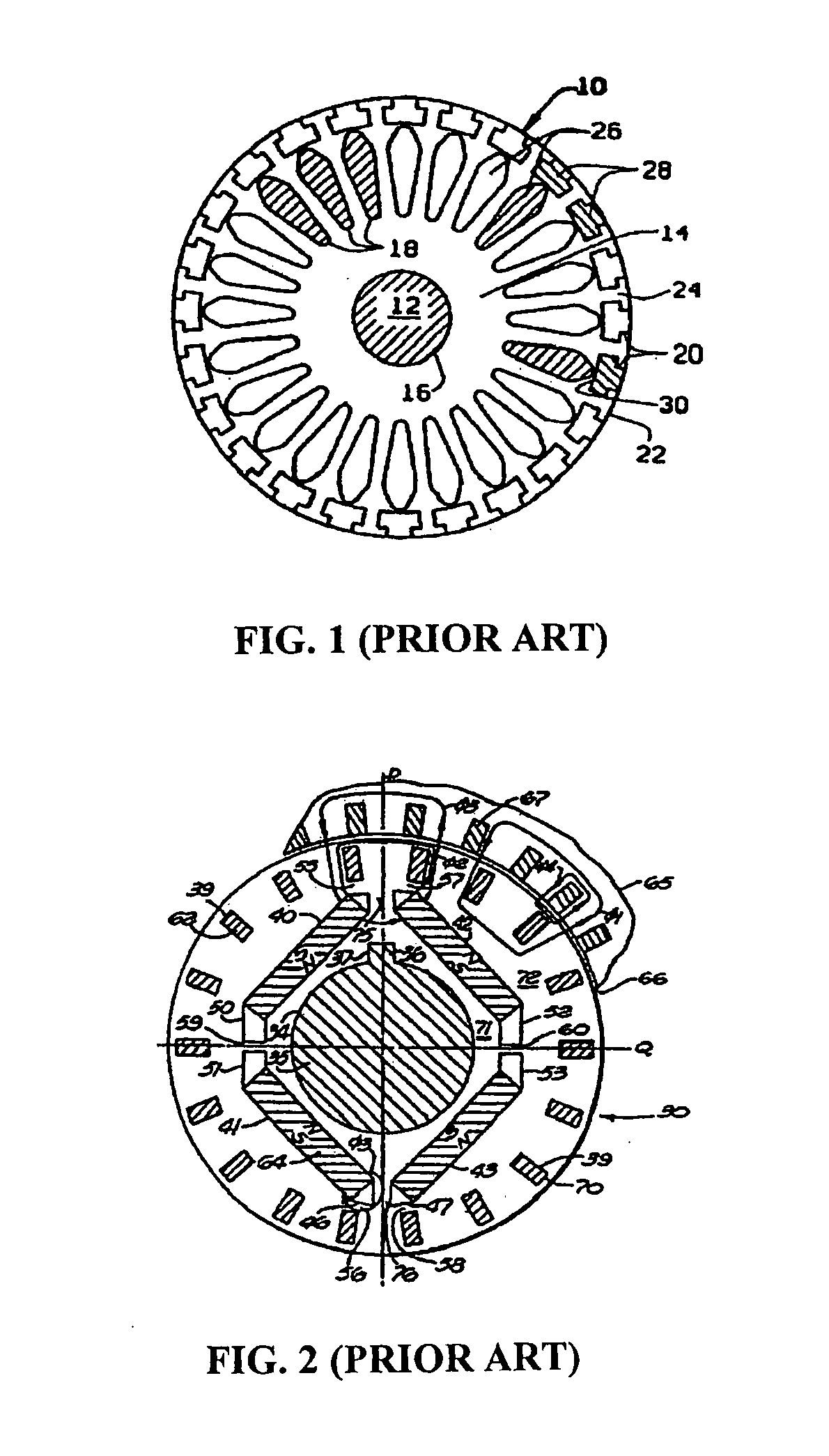
Generally, the stator provides skew channels to improve the demerit, but the winding work of the stator becomes rather difficult. FIG. 1 is the U.S. Pat. No. 5,925,727, Boyd et al. of the prior art.
However, since the rotor does not have squirrel cage structure provided, the rotor cannot be line-started without utilizing some other devices.
But, as described before, since the rotor 13 is round in shape without special designed configuration, therefore, the cogging torque as well as the vibration and noise of the motor while the motor is in operation are still relatively large.
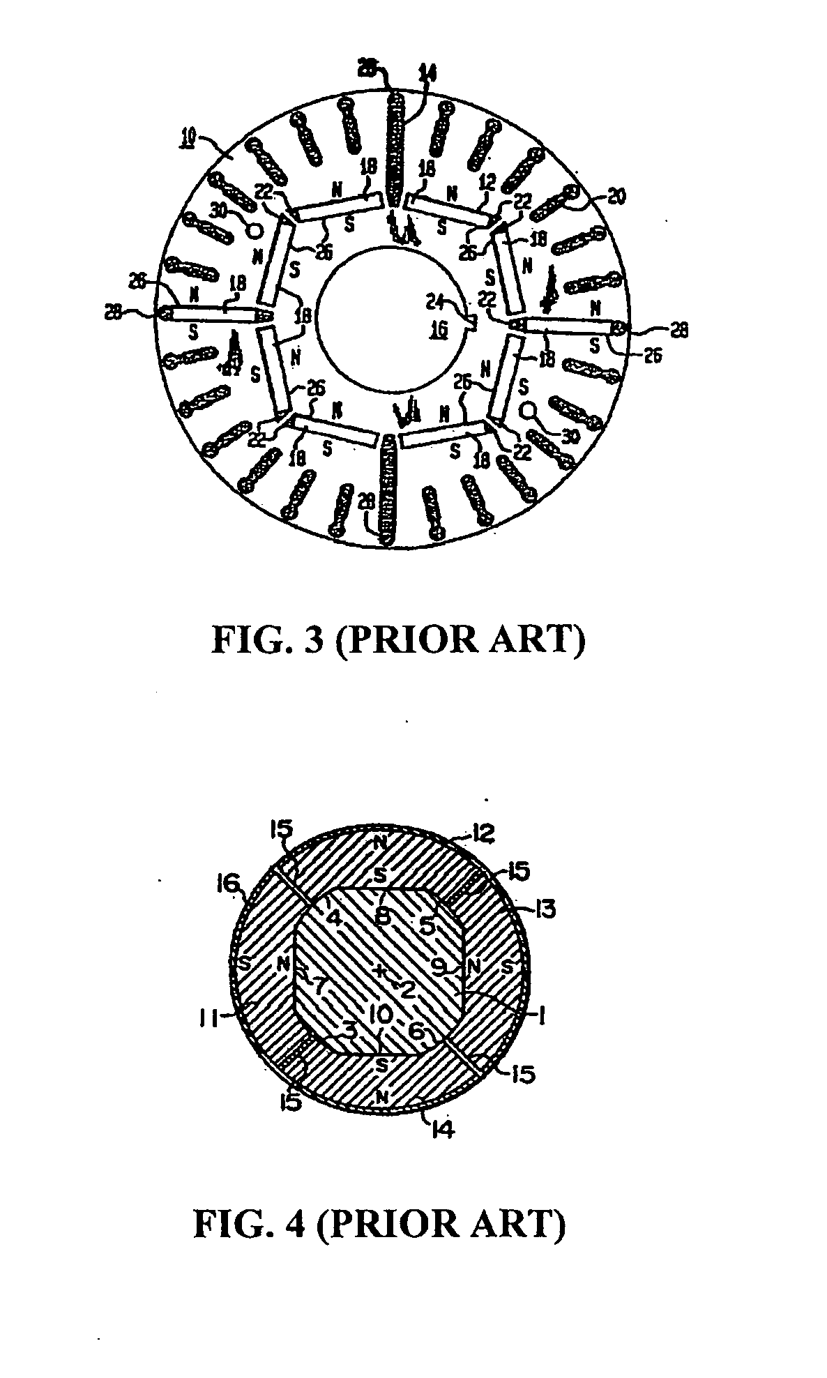
However, just how the curvature of the surface of the rotor varies is not explained anywhere in their specifications.
However, generally, among all the permanent magnets of rare earth metals having high magnetic energy products, the permanent demagnetization temperatures are less than 200° C. Placing the permanent magnets in the permanent magnet containing slots beforehand can cause the permanent magnets to be subject to demagnetization during the casting manufacturing process.
However, no explanation is given anywhere in the specification as to what kind of the curve of the arc it belongs to.
What is more, the prior art does not provide any means to adequately attenuate the magnetic flux of the magnetic pole to reduce the self-retaining torque caused by the magnetic flux of the magnetic poles.
Therefore, the prior art cannot improve the starting characteristic of the motor at the transient state during the operation from “stop” to “start” of the LSPM synchronous motor.
Furthermore, as pointed out in the preceding discussion, since the rotor does not have squirrel cage structure provided, the rotor cannot be line-started without utilizing some other devices.
The foregoing statements are the disadvantages of the prior art.
Method used
Image
Click on the blue label to locate the original text in one second.
Reading with bidirectional positioning of images and text.
Examples
first embodiment
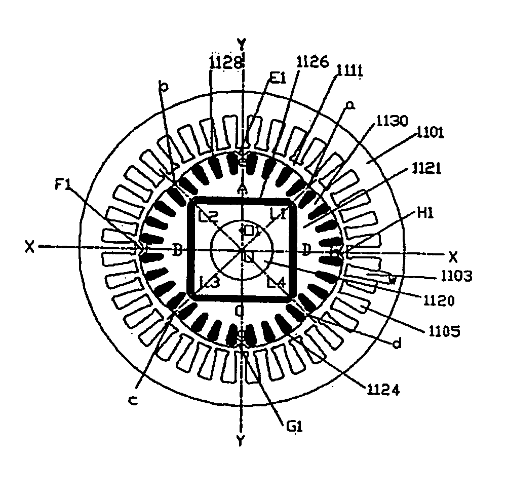
[0059] As shown again in FIG. 11, the LSPM synchronous motor 11 of the invention provides semi-circle recesses E1, F1, G1, and H1 at the midpoints e1, f1,g1, and h1 of the “first eccentric circular arcs of the surface of the magnetic poles” ab, bc, cd, and da of the fan-shaped magnetic poles A, B, C, and D. The semi-circle recesses E1, F1, G1, and H1 having diameter equals to the width w of the tooth-part 1103 of the stator 1101 and radius r=w / 2 has fillets 1136 at their both ends to connect smoothly to the “first eccentric circular arcs of the surface of the magnetic poles”1124.
second embodiment
[0060] As shown in FIG. 16 and FIG. 17, besides providing recesses E1, F1, G1, and H1 aligned with the locations of the tooth-part 1130 of the rotor 1121, the LSPM synchronous motor 11 of the invention also provides recesses E2, F2, G2, and H2 as well as E3, F3, G3, and H3 (see also FIG. 11 and FIG. 18) on each side of the recesses E1, F1, G1, and H1 having the same size and aligned with the locations of the adjacent tooth-part 1130 of the rotor 1121. This is the situation when the number of the plurality of conductive bar slots 1128 of each of the fan-shaped magnetic poles A, B, C, and D is an even number. If the number of the plurality of conductive bar slots 1128 of each of the fan-shaped magnetic poles A, B, C, and D is an odd number, the recesses E2, F2, G2, and H2 as well as E3, F3, G3, and H3 on each side of the recesses E1, F1, G1, and H1 having the same size are aligned with the locations of the adjacent conductive bar slots 1128 of the rotor 1121. Therefore, there are thre...
third embodiment
[0061] As shown in FIG. 19, in the LSPM synchronous motor 11 of the invention, the semi-circle recesses E1, F1, G1, H1 as shown in FIG. 12, as well as the semi-circle recesses E1, F1, G1, H1□E2, F2, G2, H2□ and E3, F3, G3, H3 as shown in FIG. 16 are all replaced by the “second eccentric circular arcs of the surface of the magnetic poles”1901 having center of curvature O2 offset from the center of the rotor O with the offset length OS2 of the offset OO2 and radius of curvature R2, therefore, R2−R=OS2.
[0062] As shown again in FIG. 19, in the third embodiment of the invention, the tangent points between the “second eccentric circular arcs of the surface of the magnetic poles”1901 and the “first eccentric circular arcs of the surface of the magnetic poles”1124 in the fan-shaped magnetic poles A, B, C, and D are al and a2□b1 and b2□c1 and c2□as well as d1 and d2 respectively. In other words, in the third embodiment of the invention, the “second eccentric circular arcs of the surface of t...
PUM
Abstract
The invention provides a rotor structure of line-start permanent magnet (LSPM) synchronous motor that includes a shaft; four fan-shaped magnetic poles each having a first eccentric circular arcs of the surface of the magnetic poles which has a center O1 that is offset from the center O of the rotor with an offset length OS1 and which makes the maximum thickness of the air gap roughly two to five times as much as the minimum thickness of the air gap; four permanent magnets disposing in the inner loop of each of the fan-shaped magnetic poles□a plurality of pear-shaped conductor slots disposing in equal spaces in the outer loop of the rotor in each of the fan-shaped magnetic poles and orienting in radial direction having O1 as the center for forming a squirrel cage winding; as well as four recesses at the midpoint of the first eccentric circular arcs of the surface of the magnetic poles in each of the fan-shaped magnetic poles.
Description
FIELD OF THE INVENTION [0001] The invention relates to a rotor structure of a line-start permanent magnet synchronous motor, and more particularly, to a rotor structure of a hybrid type motor combining the merits of an induction motor and a synchronous motor, and being able to lower the cogging torque and to improve the starting characteristics of a motor. BACKGROUND OF THE INVENTION [0002] The line-start permanent magnet (LSPM) synchronous motor of the prior art is a hybrid motor with its stator structure being substantially the same as that of an AC induction motor or that of an AC synchronous motor. On the other hand, the rotor structure of this hybrid motor is a combination of the squirrel cage structure in the rotor of the AC induction motor and the permanent magnet structure in the rotor of the AC permanent magnet synchronous motor. When the stator of the LSPM synchronous motor is connected to the power source, a rotating magnetic field is generated by the stator, and an induc...
Claims
Application Information
Patent Timeline
Application Date:The date an application was filed.
Publication Date:The date a patent or application was officially published.
First Publication Date:The earliest publication date of a patent with the same application number.
Issue Date:Publication date of the patent grant document.
PCT Entry Date:The Entry date of PCT National Phase.
Estimated Expiry Date:The statutory expiry date of a patent right according to the Patent Law, and it is the longest term of protection that the patent right can achieve without the termination of the patent right due to other reasons(Term extension factor has been taken into account ).
Invalid Date:Actual expiry date is based on effective date or publication date of legal transaction data of invalid patent.

