High-frequency oscillation element, magnetic information recording head, and magnetic storage device

a technology of high-frequency oscillation and magnetic information, which is applied in special recording techniques, generators/motors, instruments, etc., can solve the problems of difficult implementation of energy radiation by heat assistance methods for high-density magnetic recording, and achieve the effect of increasing the temperature of the medium or the memory cell

Active Publication Date: 2005-02-03
KK TOSHIBA
View PDF19 Cites 158 Cited by
  • Summary
  • Abstract
  • Description
  • Claims
  • Application Information

AI Technical Summary

Benefits of technology

[0015] The energy of the magnetic vibration having developed in the magnetic material because of magnetic resonance is immediately transmitted to magnetization of a neighboring medium or magnetization of a memory cell of th

Problems solved by technology

As described above, the heat assistance method for high-density magnetic

Method used


Image

  • High-frequency oscillation element, magnetic information recording head, and magnetic storage device
  • High-frequency oscillation element, magnetic information recording head, and magnetic storage device
  • High-frequency oscillation element, magnetic information recording head, and magnetic storage device

Examples


first embodiment

[0024] (First Embodiment)

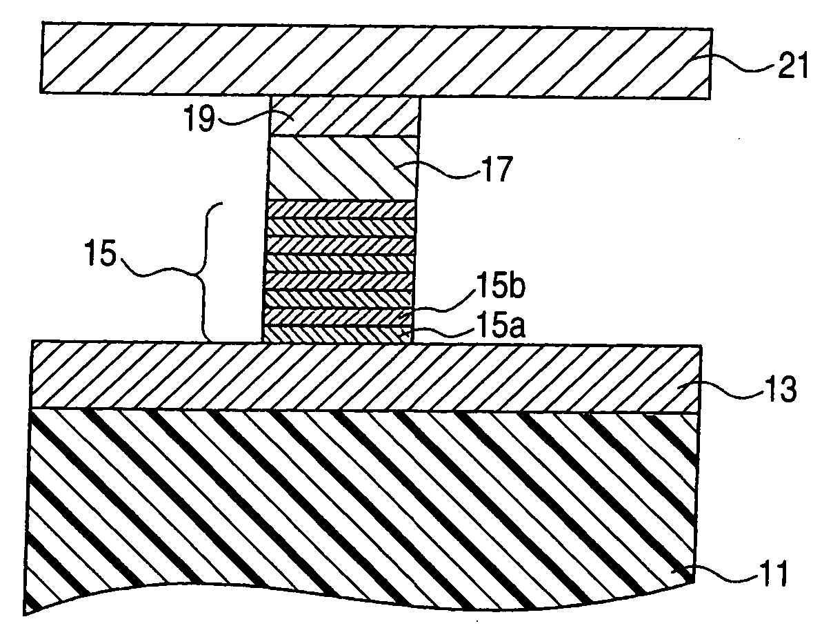
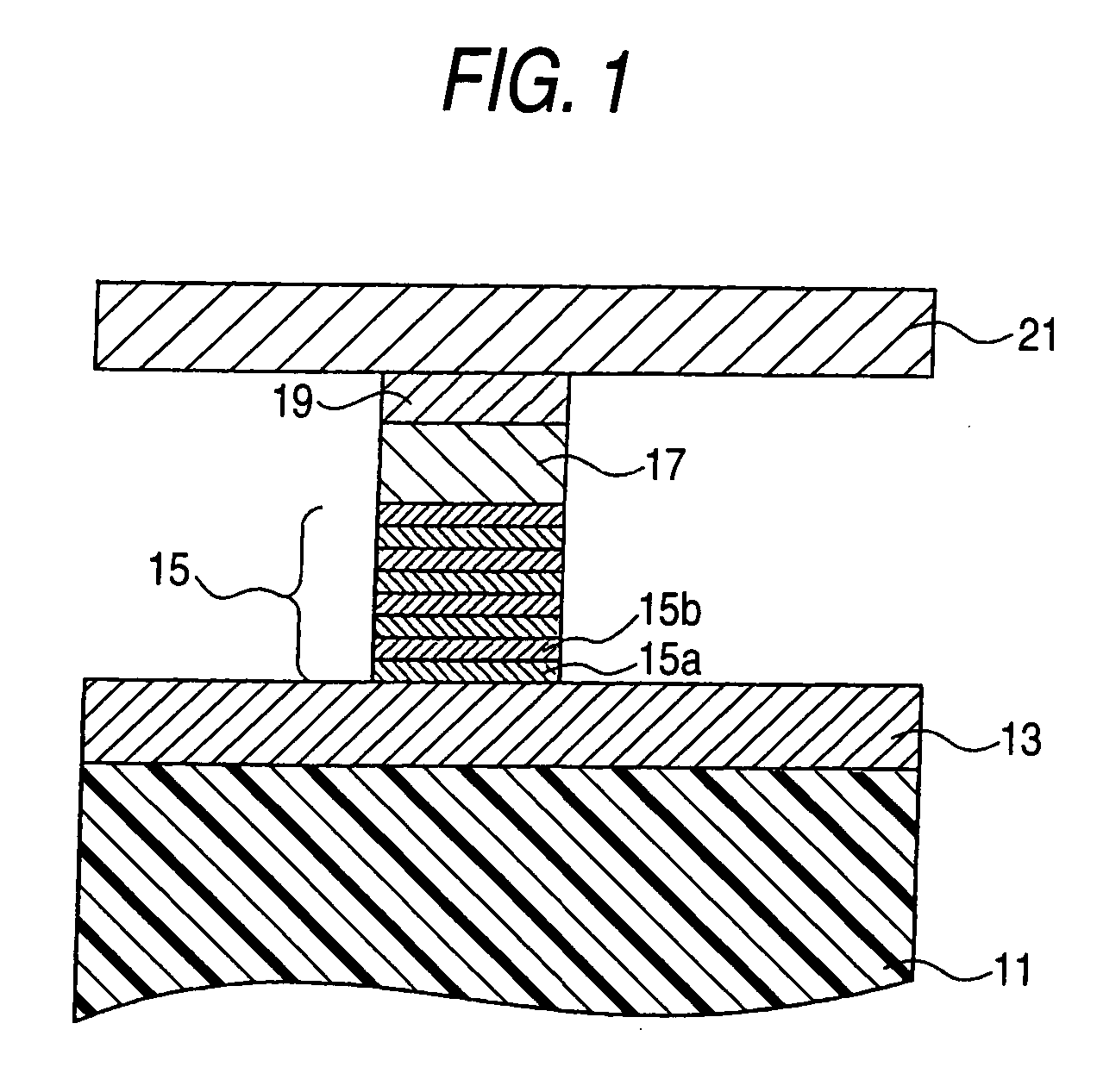
[0025]FIG. 1 is a diagrammatic cross-sectional view for explaining a high-frequency oscillation element according to a first embodiment of the invention.

[0026] This high-frequency oscillation element is formed on a substrate 11 shown in FIG. 1, and has a lower electrode 13 serving also as a radiating plate, an artificial lattice film (also called an “artificial antiferromagnetic film”) formed on the lower electrode 13, a nonmagnetic film 17, a ferromagnetic film 19, and an upper electrode 21 serving also as a radiating plate. The lower electrode 13 and the upper electrode 21 serve also as the radiating plates and, therefore, extend horizontally across the paper plane of FIG. 1 and are connected at their end portions to a current supply circuit which controls a current flow to the element, or the like.

[0027] The lower electrode 13 and the upper electrode 21 can be provided with a radiating plate and wiring independently from the electrodes. In such a case, ...

first example

[0073] (First Example)

[0074] A first example of the present invention will now be described by reference to a diagrammatic cross-sectional view of FIG. 3.

[0075]

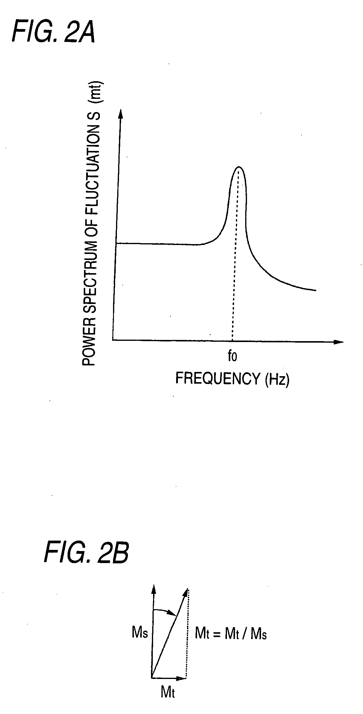
[0076] In this example, thermal fluctuations stemming from magnetization of the ferromagnetic material were measured.

[0077] First, a multilayer film was formed on a silicon substrate 31 by means of sputtering film growth and electron lithography. This multilayer film has, in sequence from the substrate 31, a non-magnetic Cu layer 33, a ferromagnetic Co layer 35; a non-magnetic Cu layer 37; a ferromagnetic Fe layer 39; a non-magnetic Cu layer 41; a non-magnetic Au layer 43; and a non-magnetic Cu layer 45.

[0078] Thicknesses-of the respective layers are as follows: the Cu layer 33 has a thickness of about 100 nm; the Co layer 35 has a thickness of about 50 nm; the Cu layer 37 has a thickness of about 30 nm; the Fe layer 39 has a thickness of about 1 nm; the Cu layer 41 has a thickness of about 10 nm; the Au layer 43 has a thi...


PUM


Abstract

A high-frequency oscillation element has a ferromagnetic material which exhibits thermal fluctuation of magnetization and generates spin fluctuations in conduction electrons, a nonmagnetic conductive material which is laminated on the first magnetic material and transfers the conduction electrons, a magnetic material which is laminated on the nonmagnetic conductive material, generates magnetic resonance upon injection of the conduction electrons, and imparts magnetic dipole interaction to magnetization of a neighboring magnetic area by means of magnetic vibration stemming from the magnetic resonance, a first electrode electrically coupled with the first magnetic material, and a second electrode electrically coupled with the second magnetic material.

Description

CROSS-REFERENCE TO RELATED APPLICATIONS [0001] This application is based upon and claims the benefit of priority from the prior Japanese Patent Applications No. 2003-188875, filed on Jun. 30, 2003, the entire contents of which are incorporated herein by reference. BACKGROUND OF THE INVENTION [0002] 1. Field of the Invention [0003] The present invention relates to a high-frequency oscillation element to be used in a magnetic sensor, as well as to a magnetic information recording head and a magnetic storage device, both pertaining to high-density magnetic recording. [0004] 2. Description of the Related Art [0005] Since the inception of a GMR head employing a giant magnetoresistance effect (GMR effect), recording density of magnetic recording has been increased at a rate of about 100% per year. GMR elements include a spin-valve-type element and an artificial-lattice-type element. [0006] The spin-valve-type element has a multilayer film including a ferromagnetic layer / nonmagnetic layer / ...

Claims


Application Information

Patent Timeline
IPC IPC(8): G11B5/02G11B5/127H01L21/8246H01L27/105H03B15/00H03B28/00
CPCG11B5/314H03B15/006G11B2005/0005
Inventor SATO, RIEMIZUSHIMA, KOICHI
Owner KK TOSHIBA
Why Eureka
Try Eureka