
Imaging system, methodology, and applications employing reciprocal space optical design

a reciprocal space and optical design technology, applied in the field of image and optical systems, can solve the problems of machine-vision or computer-based image display from the above image sensor displayed on a monitor or other output display device, and the image may not be of quality perceived by the human observer through the eyepiece, so as to facilitate the imaging performance of optical imaging systems, increase the effective resolution of magnification, and increase the working distance

Inactive Publication Date: 2005-02-03
PIXEL MATCHED HLDG
View PDF36 Cites 49 Cited by
  • Summary
  • Abstract
  • Description
  • Claims
  • Application Information

AI Technical Summary

Benefits of technology

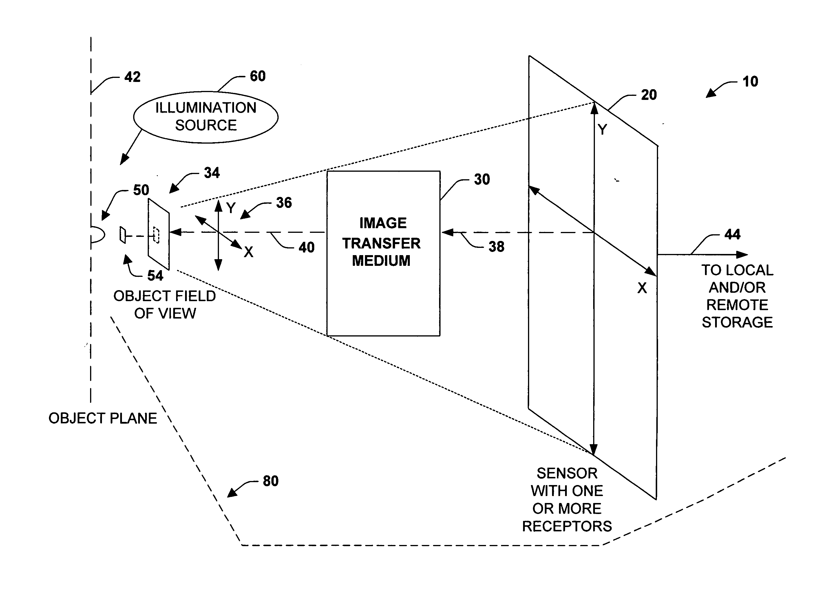
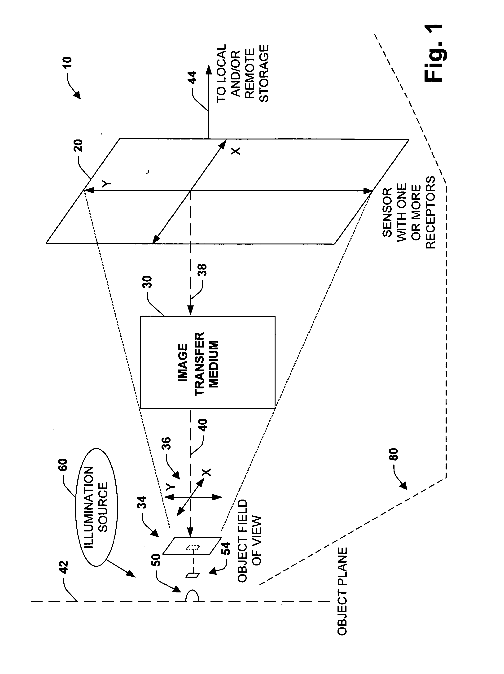
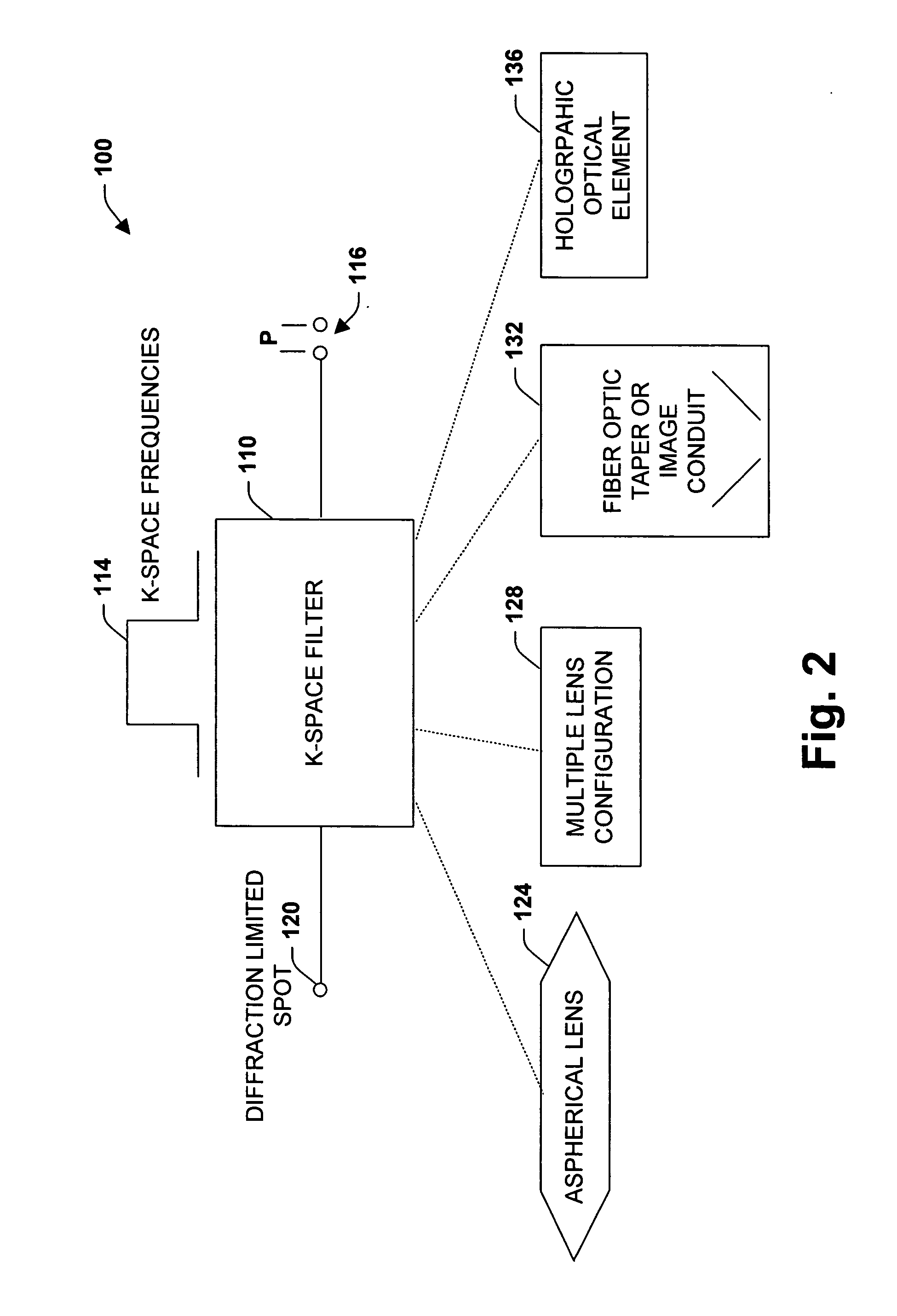
"The present invention is a system and methodology that improves the performance of optical imaging systems by adapting the image transfer medium to the sensor. This results in a transformation into k-space, which allows for a more efficient use of space and mitigates limitations associated with conventional systems. The invention achieves higher effective resolved magnification, larger working distances, increased absolute spatial resolution, increased depth of field, and oil immersion objectives and eye pieces not required. The k-space design acts as an effective \"Intrinsic Spatial Filter\" and allows for a one-to-one correspondence between image sensor receptors and projected object plane units. The invention can be used in various portable, stand-alone, or combination applications, such as remote medicine or industrial applications where an image is generated in one location and transmitted to another location for analysis."

Problems solved by technology

Connecting a Machine Vision Sensor, such as a Charge Coupled Device (CCD) sensor, to the microscope so that an image may be viewed on a monitor presents difficulties.
As a result, conventional optical systems for magnifying, observing, examining, and analyzing small items often require the careful attention of a technician monitoring the process through an eyepiece.
It is for this reason, as well as others, that Machine-Vision or computer-based image displays from the aforementioned image sensor displayed on a monitor or other output display device are not of quality perceived by the human observer through the eyepiece.

Method used


Image

  • Imaging system, methodology, and applications employing reciprocal space optical design
  • Imaging system, methodology, and applications employing reciprocal space optical design
  • Imaging system, methodology, and applications employing reciprocal space optical design

Examples


Embodiment Construction

The present invention relates to an optical and / or imaging system and methodology. According to one aspect of the present invention, a k-space filter is provided that can be configured from an image transfer medium such as optical media that correlates image sensor receptors to an optical or image transfer medium. A variety of illumination sources can also be employed to achieve one or more operational goals and for versatility of application. The k-space design of the imaging system of the present invention promotes capture and analysis (e.g., automated and / or manual) of images having a high Field Of View (FOV) at substantially high Effective Resolved Magnification as compared to conventional systems. This can include employing a small Numerical Aperture (NA) associated with lower magnification objective lenses to achieve very high Effective Resolved Magnification. As a consequence, images having a substantially large Depth Of Field (DOF) at very high Effective Resolved Magnificat...


PUM


Abstract

An imaging system, methodology, and various applications are provided to facilitate optical imaging performance. The system includes a sensor having one or more receptors and an image transfer medium to scale the sensor and receptors in accordance with resolvable characteristics of the medium. A computer, memory, and / or display associated with the sensor provides storage and / or display of information relating to output from the receptors to produce and / or process an image, wherein a plurality of illumination sources can also be utilized in conjunction with the image transfer medium. The image transfer medium can be configured as a k-space filter that correlates a pitch associated with the receptors to a diffraction-limited spot associated with the image transfer medium, wherein the pitch can be unit-mapped to about the size of the diffraction-limited spot.

Description

TECHNICAL FIELD The present invention relates generally to image and optical systems, and more particularly to a system and method to facilitate imaging performance via an image transfer medium that projects characteristics of a sensor to an object field of view. BACKGROUND OF THE INVENTION Microscopes facilitate creating a large image of a tiny object. Greater magnification can be achieved if the light from an object is made to pass through two lenses compared to a simple microscope with one lens. A compound microscope has two or more converging lenses, placed in line with one another, so that both lenses refract the light in turn. The result is to produce an image that is magnified with improved quality in Resolved Magnification and other image parameters than either lens could alone. Light illuminating the object first passes through a short focal length lens or lens group, called the objective, and then travels on some distance before being passed through a longer focal length...

Claims


Application Information

Patent Timeline
Patent Type & Authority Applications(United States)
IPC IPC(8): G02B21/00G02B21/36G06T3/00H01L27/00
CPCG02B21/0008G02B21/02G02B21/365G02B21/16G02B21/24G02B21/088
Inventor CARTLIDGE, ANDREW G.FEIN, HOWARD
Owner PIXEL MATCHED HLDG
Learn More