Method and system for path identification in packet networks

Active Publication Date: 2005-02-03
SONS OF INNOVATION LLC
View PDF20 Cites 154 Cited by
  • Summary
  • Abstract
  • Description
  • Claims
  • Application Information

AI Technical Summary

Benefits of technology

[0012] In accordance with one embodiment of the present invention, a method of identifying a path of travel for a packet in a multi-area domain operated according to a link state routing protocol includes the step of receiving topology information from a plurality of individual areas in a domain. It also includes the steps of identifying a plurality of intra-area least cost paths from the topology information, and assembling a subset of the plurality of intra-area least cost paths into an end-to-end path between a starting address and a destination address. Each least cost path preferably comprises a series of routers, with links or networks between routers.
[0013] Optionally and preferably, in the identifying step, at least one exit point from the first area through which the destination address is reachable is identified, at least one least cost path segment within the first area between the starting address and at least one of the exit points is constructed, and at least one of the least cost path segments is selected to result in at least one selected first area least cost segment. As an additional option, the exit point from first area may be the destination address. The identifying step may also include identifying all exit points from the first area through which the destination address is reachable.
[0014] The identifying step may also include the step of, for at least one of the exit points associated with at least one of the selected least cost path segments, identifying a second area within the domain to which said at least one exit point is connected. The identifying step may also include the steps of identifying at least one exit point from the second area through which the destination address is reachable, constructing at least one least cost path segment within the second area between the at least one exit point of the first area and at least one exit point of the second area, and selecting at least one of the least cost segments within the second area to result in at least one selected second area least cost segment. Under this option, the assembling step may include connecting one of the selected first area least cost segments and o

Problems solved by technology

However, this distributed mode of operation and the associated robustness it affords come at a price.
For example, accuracy in characterizing the behavior of the network at any given time is a complex task.
Because of this, many of the network management functions that are available for networks based on more traditional technologies, e.g., connection-oriented such as frame relay or asynchronous transfer mode (ATM), are difficult if not impossible to replicate in IP networks.
Again, this makes it more difficult for a network administrator to precisely identify the path that the traffic between, for example, two customer sites, is following when traversing the network.
As a consequence, upon identifying a highly congested link, a network administrator has no or only limited visibility into which customers may be experiencing poor performance as a result of this congestion.
Similarly, in the presence of a link failure, identifying which customers are immediately affected as well as predicting which ones may also experience a change in service performance shortly after the failure is again a very complex task i

Method used


Image

  • Method and system for path identification in packet networks
  • Method and system for path identification in packet networks
  • Method and system for path identification in packet networks

Examples


Embodiment Construction

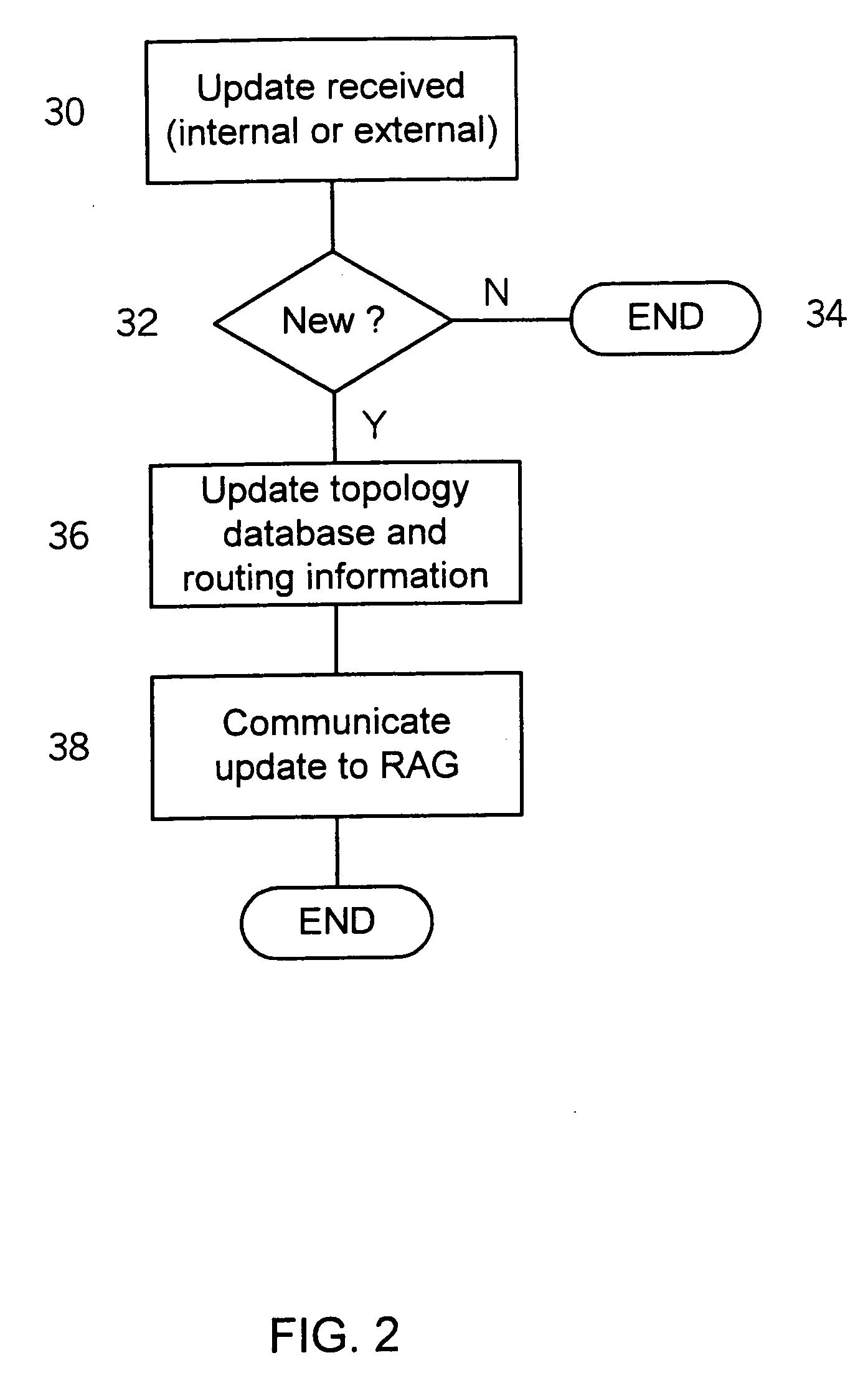
[0033] A preferred embodiment of the present invention provides an improved method and system for monitoring, tracking, and / or predicting the routing path of one or more packets under an IP protocol.

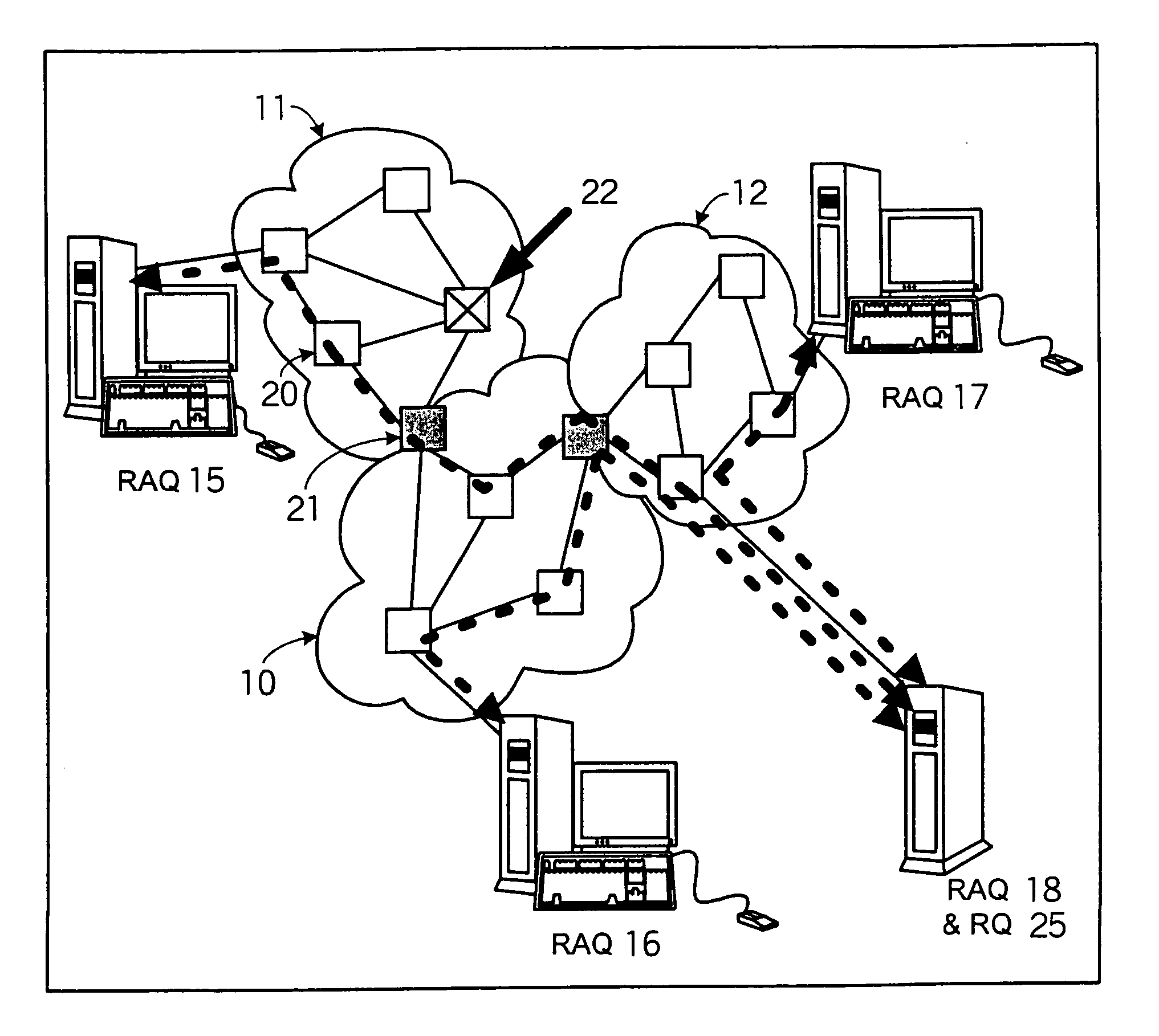
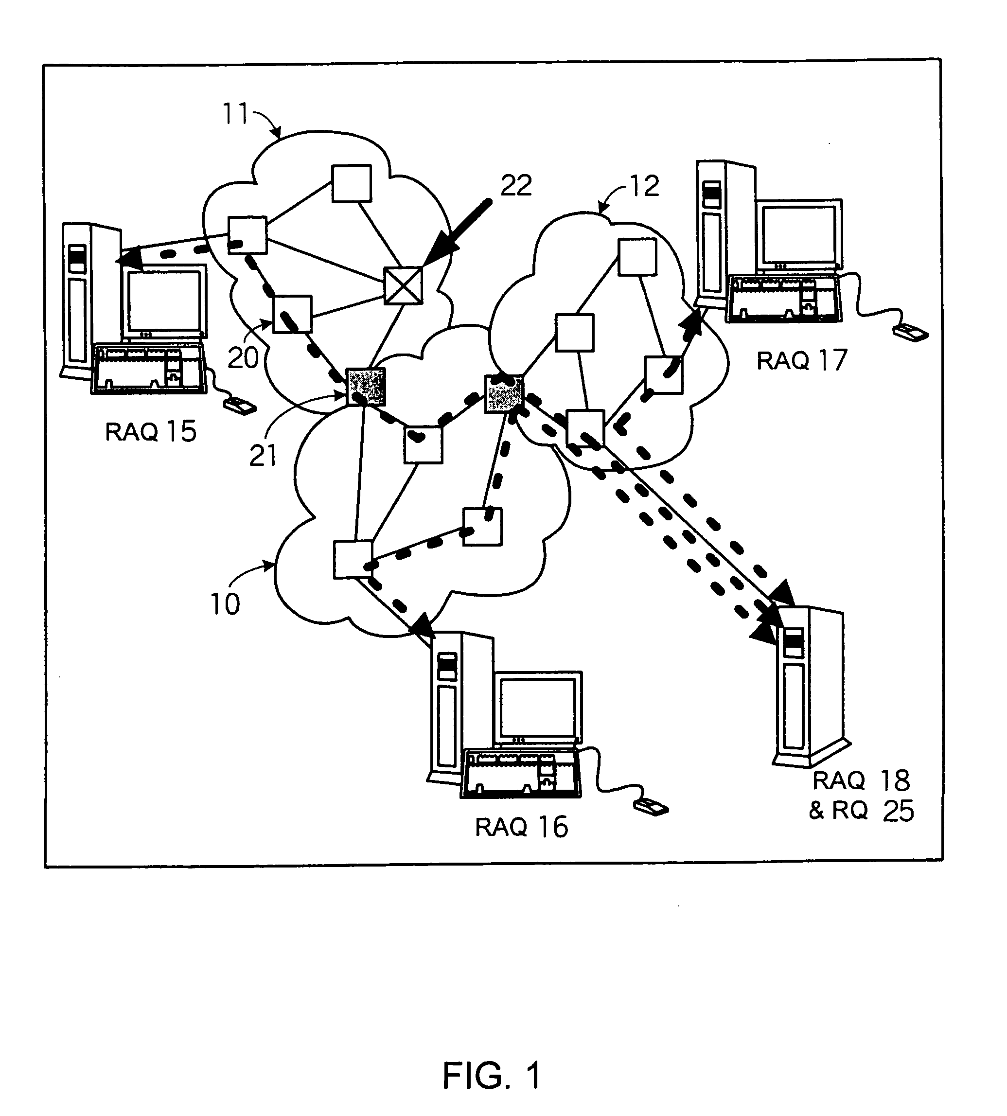
[0034] The present invention allows a network administrator, network monitoring system, or other human or automated user to identify the path or paths followed or expected to be followed by any packet traveling though an AS, where the packet has a known entry point or address and a known or anticipated destination address. The destination address is associated with a routing entry, typically from a routing table, and the present invention constructs the path that was or is expected to be followed through the routing domain by the packet associated with the routing entry. Optionally and preferably, when more than one path is possible, the invention is capable of constructing the complete set of possible paths, any of which the packet may follow.

[0035]FIG. 1 illustrates an exemplary AS, ...


PUM


Abstract

A method and system for extracting and building end-to-end route information in a multi-area Internet protocol (IP) autonomous system (AS) is disclosed. The method and system enable a user, such as a network administrator, to explicitly identify a full set of paths (links and routers) that a given IP packet would potentially traverse from its entry point in the source area of the AS where it originates until its exit point in its intended destination area.

Description

FIELD OF THE INVENTION [0001] The present invention relates generally to a method and system for acquiring information from a packet communications network. More particularly, the present invention relates to a method and system for determining the set of links and routers that are traversed by traffic to and / or from an individual user of a packet communications network. BACKGROUND OF THE INVENTION [0002] An Internet protocol (IP) network is a large distributed system in which individual routers automatically adjust their decisions on how to forward packets based on information they learn from their neighbors about the state of the network. This design permits rapid recovery in case of link or router failures by allowing affected routers to re-route packets around the failure as soon as they discover it. [0003] However, this distributed mode of operation and the associated robustness it affords come at a price. For example, accuracy in characterizing the behavior of the network at a...

Claims


Application Information

Patent Timeline
IPC IPC(8): H04L12/24H04L12/56H04N7/26H04N11/04
CPCH04L41/12H04L45/02H04L45/04H04L45/12H04N19/184H04L45/26H04N11/042H04N19/186H04L45/123H04L45/03
Inventor RAJAN, RAJENDRANGUERIN, ROCH
Owner SONS OF INNOVATION LLC
Why Eureka
Try Eureka