Manufacturing processes of catalyst layer for fuel cell

a technology of catalyst layer and manufacturing process, which is applied in the direction of physical/chemical process catalyst, cell component, metal/metal-oxide/metal-hydroxide catalyst, etc., can solve the problem of long time required for reducing the loading level of platinum catalyst particles, the problem of commercialization to be overcome, and the effect of shortening the aging tim

Inactive Publication Date: 2005-02-03
GS YUASA INT LTD
View PDF10 Cites 21 Cited by
  • Summary
  • Abstract
  • Description
  • Claims
  • Application Information

AI Technical Summary

Benefits of technology

[0007] The feature of the process for ultra-low alloy catalyst loading electrode according this invention is to reduce its alloy formation period of aging process subsequent to hydrogen reduction process of catalyst ions after ion exchange process of their ions and proton in the cluster of the polymer electrolyte on the surface of the carbon powder. The process is able to drastically shorten the aging time with temperature rise beyond 200° C. up to 400° C. under hydrogen atmosphere for the formation of Pt—Ru b

Problems solved by technology

The biggest problem to be overcome for its commercialization is high cost.
This problem is strongly concerned with the usage of large amount of precious metal of platinum as catalyst particles for electrodes of fuel cells.
Therefore, the reduction of loading level of platinum catalyst particles has been required for a long time.
The catalyst of Pt in the anode of PEFC is poisoned by the small amount of CO and t

Method used


Image

  • Manufacturing processes of catalyst layer for fuel cell
  • Manufacturing processes of catalyst layer for fuel cell
  • Manufacturing processes of catalyst layer for fuel cell

Examples


example 1

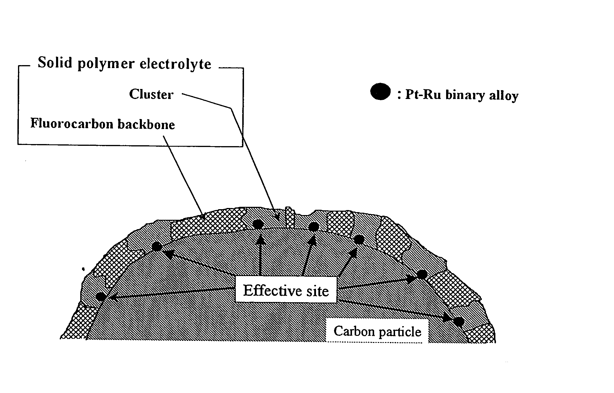
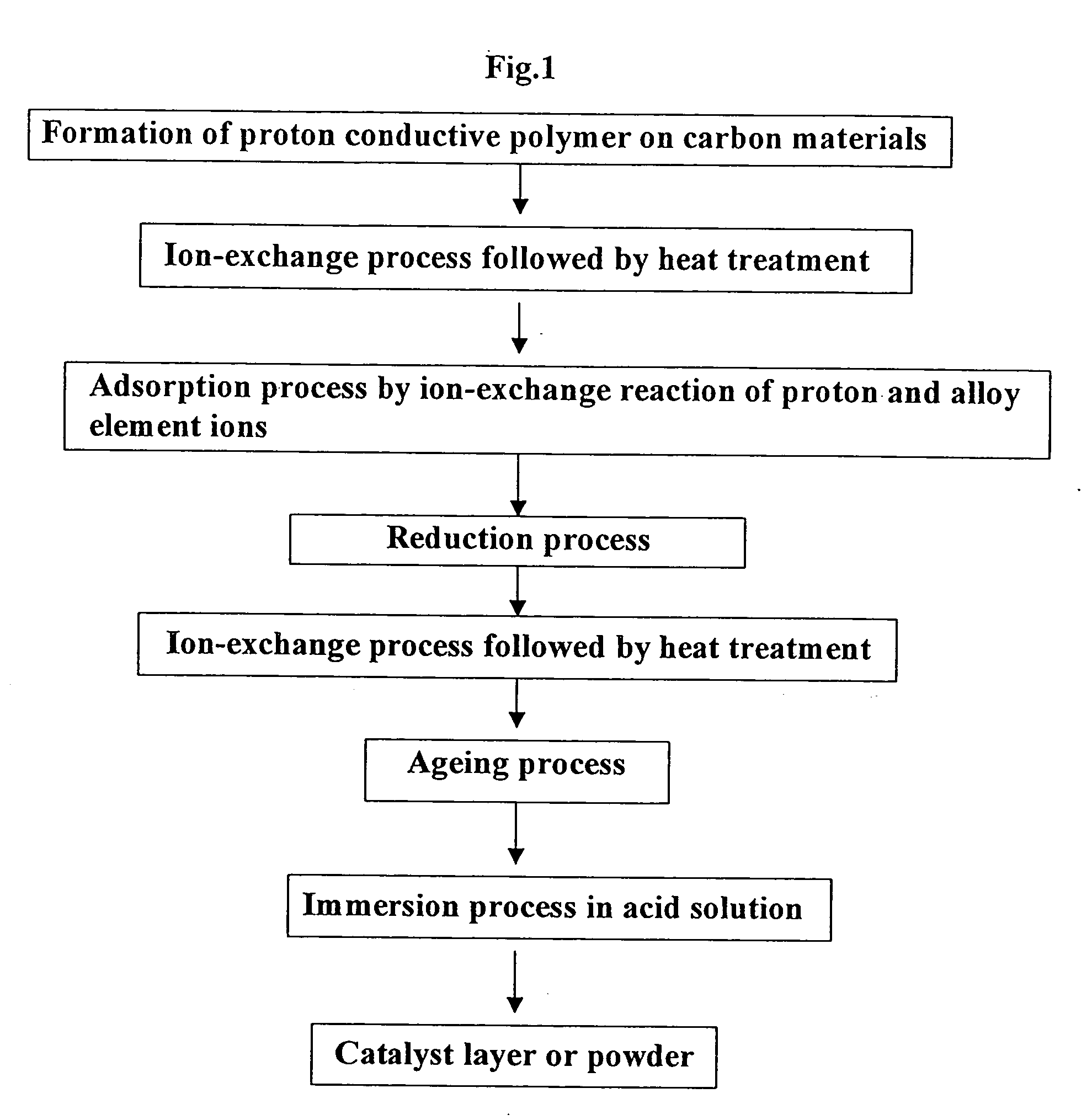
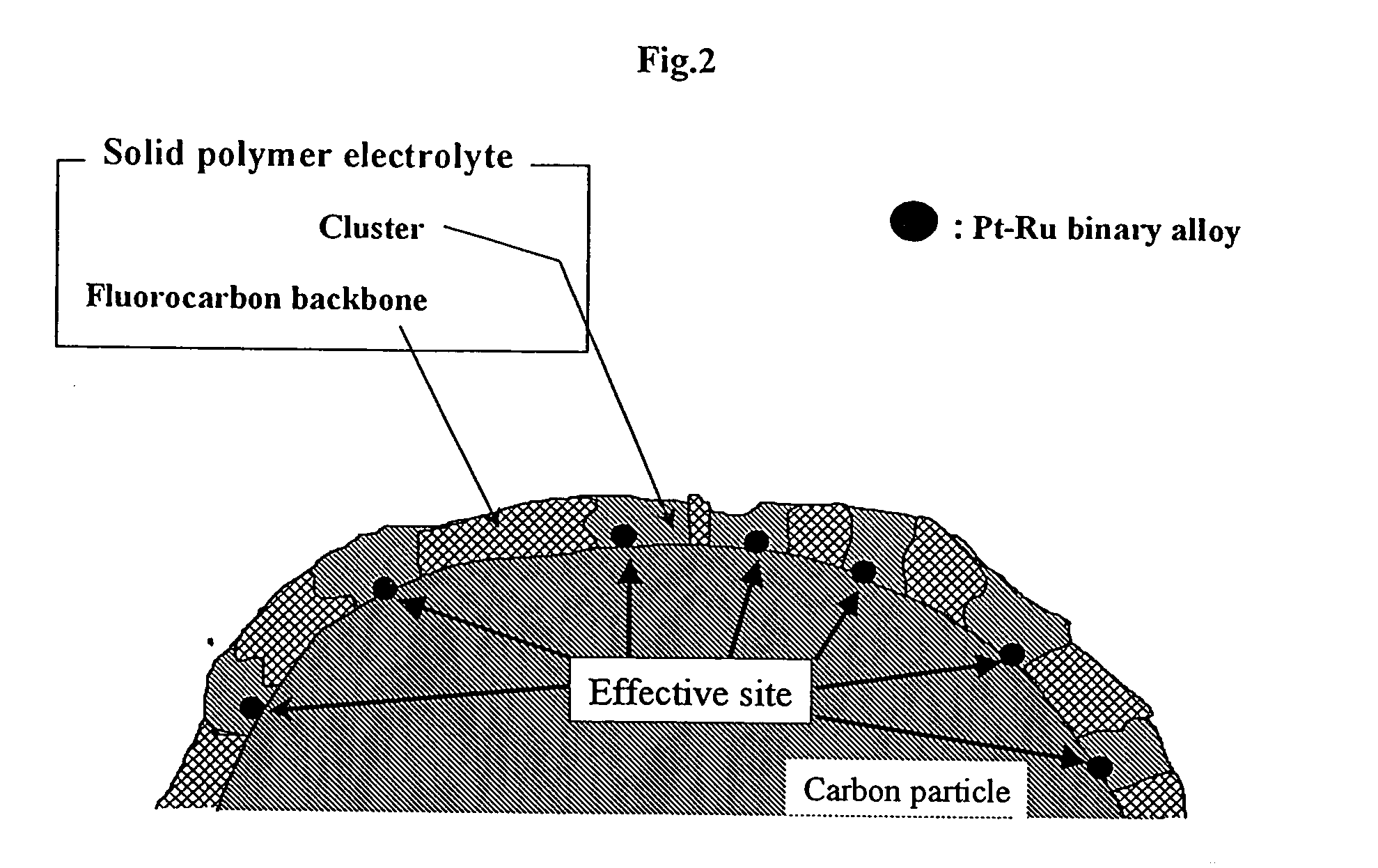
[0021] A mixture of 54 g of a proton conductive polymer resin solution (5 mass % Nafion solution manufactured by Aldrich Inc.) and 5 g of carbon powder (Vulcan XC-72 manufactured by Cabot Corp.) was kneaded and concentrated with heating at 65° C. to make a paste. The paste was then applied to FEP (Tetra fluoroethylene hexa fluoro propylene copolymer) sheet to form the paste layer followed by drying at 25° C. The dry layer was immersed into mixed aqueous solution containing 3.8×10⁻² mol l−1 of [Pt(NH3)4]Cl2 and 1.3×10⁻² mol l−1 of [Ru(NH3)6]Cl3 for 24 hours to substitute [Pt(NH3)4]2+ ion and [Ru(NH3)6]3+ ion for proton in the cluster of proton conductive polymer by ion-exchange reaction followed by washing process with de-ionized water. The platinum and ruthenium ion was reduced by hydrogen atmosphere at 200° C. for 24 hours to form the premature metallic platinum-ruthenium binary alloy. The layer was then immersed in 5.0×10⁻¹ mol l−1 of KOH for 24 hours to substitute K+ ion for prot...

example 2

[0022] The single PEFC (B) according to the present invention was prepared using the anode catalyst layer of Pt—Ru 0.022 mg cm−2 in the same process as the case of example 1 besides 5.0×10⁻¹ mol l−1 of NaOH instead of 5.0×10⁻¹ mol l−1 KOH.

example 3

[0023] The single PEFC(C) according to the present invention was prepared using the anode catalyst layer with Pt—Ru 0.022 mg cm−2 in the same process as the case of example 1 besides 5.0×10⁻¹ mol l−1 of Ca(OH)2 instead of 5.0×10⁻¹ mol l−1 KOH, though the colloidal particle was observed.


PUM

PropertyMeasurementUnit
Temperatureaaaaaaaaaa

Abstract

The feature of the process for ultra-low alloy catalyst loading electrode according this invention is to reduce its alloy formation period of aging process subsequent to hydrogen reduction process of catalyst ions after ion exchange process of their ions and proton in the cluster of the polymer electrolyte on the surface of the carbon powder. The process is able to drastically shorten the aging time with temperature rise beyond 200° C. up to 400° C. under hydrogen atmosphere for the formation of Pt—Ru binary alloy for example catalyst by the additional processes of pre-treatment of K+, Na+, Li+, Rb+, Cs+, Mg2+, Ca2+, Ba2+, Fe2+, Sr2+, Ra2+, Cu2+, Ag+, Zn2+, Ni2+, and Co2+ ions substitution for proton before the hydrogen reduction process. More preference, the further post-treatment of K+, Na+, Li+, Rb+, Cs+, Mg2+, Ca2+, Ba2+, Fe2+, Sr2+, Ra2+, Cu2+, Ag+, Zn2+, Ni2+, and Co2+ ions substitution for proton before the ion exchange process. This new process is little harmful to the CO tolerance performance of PEFC.

Description

TECHNICAL FIELD [0001] The present invention relates to manufacturing processes of catalyst layer for fuel cell. BACKGROUND OF ART [0002] A polymer electrolyte fuel cell (PEFC) is expected as a clean power source for automobiles as well as stationary applications because of its operation at moderate temperature below 100° C. in contrast with another type of fuel cells. The biggest problem to be overcome for its commercialization is high cost. This problem is strongly concerned with the usage of large amount of precious metal of platinum as catalyst particles for electrodes of fuel cells. Therefore, the reduction of loading level of platinum catalyst particles has been required for a long time. A lot of efforts have been made for the minimum loading level of platinum by the development of well-dispersed very small size particles with high utilization. Recently the new technology of ultra-low platinum loading electrode (ULPLE) of which platinum catalyst particle is loaded mainly on th...

Claims


Application Information

Patent Timeline
IPC IPC(8): B05D5/12H01M4/86H01M4/88H01M4/92H01M8/10
CPCH01M4/8647H01M4/921Y02E60/50H01M2008/1095H01M4/926
Inventor YASUNAGA, YOSHINOBUHITOMI, SHUJI
Owner GS YUASA INT LTD
Why Eureka
Try Eureka