
Biosensor and methods of use thereof

a biosensor and sensor technology, applied in the field of biosensors, can solve the problems of increasing the likelihood of patient acceptance, insufficient four to seven glucose measurements per day,

Inactive Publication Date: 2005-02-03
ANIMAS TECH +1
View PDF34 Cites 173 Cited by
  • Summary
  • Abstract
  • Description
  • Claims
  • Application Information

AI Technical Summary

Benefits of technology

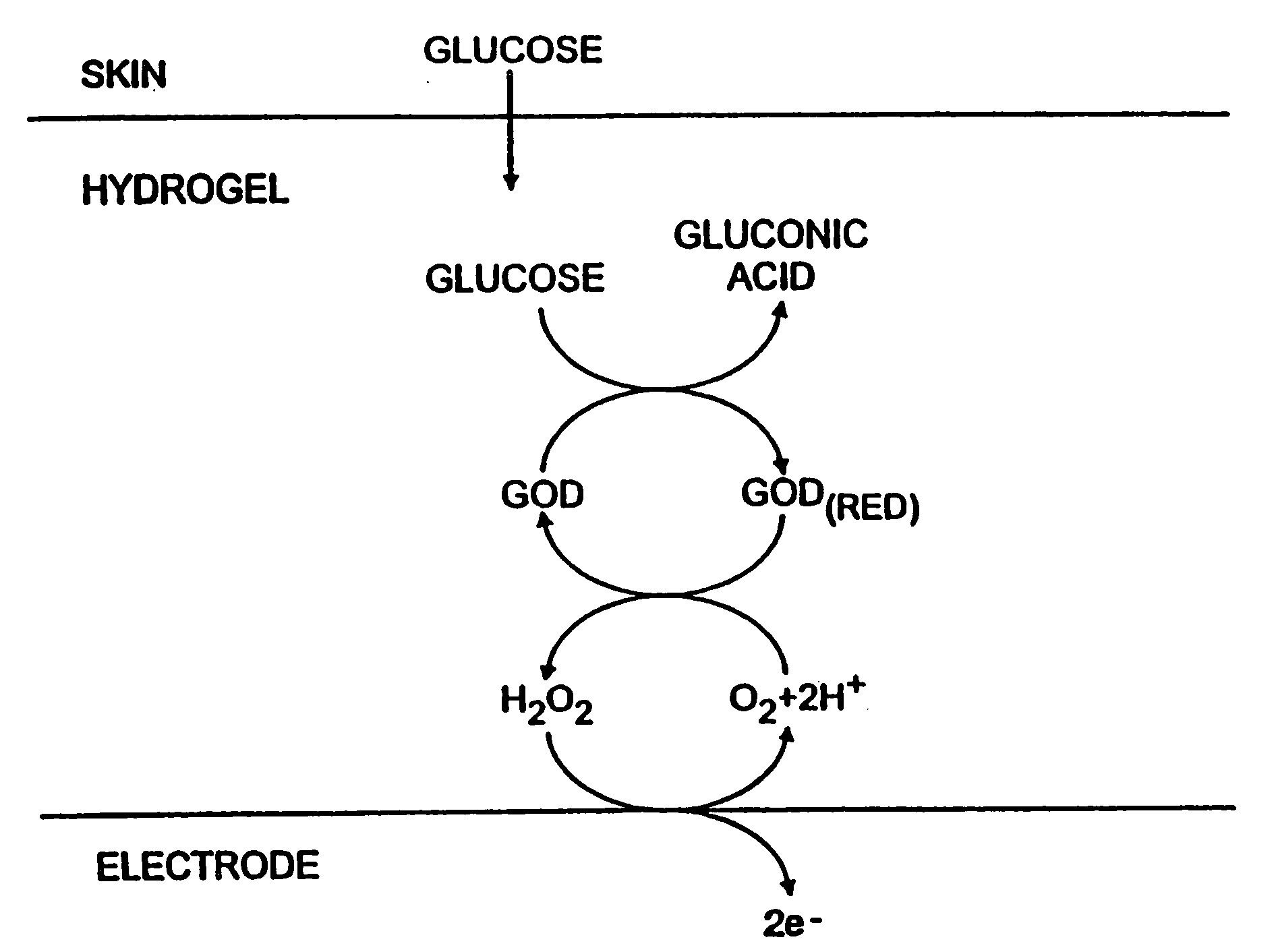
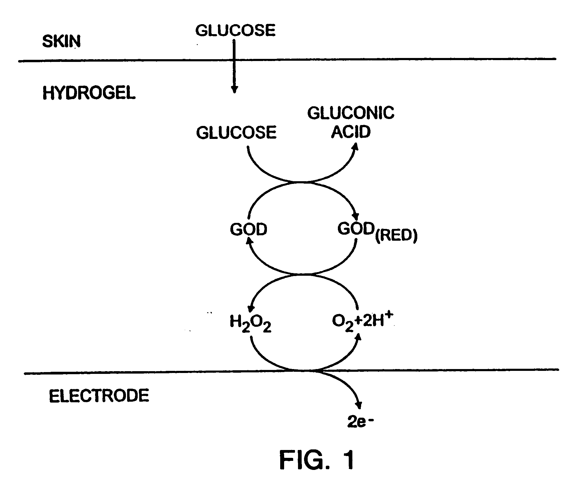
[0011] Accordingly, the present invention provides an efficient sampling system for detecting and / or measuring the concentration of a transdermally extracted analyte. The invention represents an improvement over prior noninvasive monitoring techniques and devices by providing an automatic sampling system coupled with a highly sensitive biosensor for determining the concentration of a target analyte present in an aqueous biological system. The sampling system extracts small amounts of a target analyte via transdermal methods, and then senses and / or quantifies the concentration of the target analyte. Sampling is carried out in a continual manner, allowing quantification to be carried out even when a target analyte, extracted from the biological system, is obtained at a sub-millimolar (sub-mM) concentration.
[0012] The advantages provided by the invention are thus several fold. For example, the noninvasive nature of the sampling system significantly increases the likelihood of patient acceptance. In the particular context of blood glucose monitoring, better glycemic control can be achieved by taking frequent blood glucose measurements on a daily basis, and using that information to determine the amount and frequency of insulin administration. Use of the noninvasive sampling system of the invention helps increase the likelihood that such frequent measurements will be taken. In addition, the automatic sampling provided by the instant sampling system, particularly when taken over an extended period of time (e.g., 24 hours or more) can be used to monitor concentration swings previously not detectable using prior devices. Again in the context of blood glucose monitoring, it is now believed that even four to seven glucose measurements per day may be insufficient to reflect the diurnal glucose level variation in many diabetics. Using the instant sampling system to automatically measure blood glucose at, for example, a frequency of once per hour, allows monitoring of previously unrecognizable glucose swings, particularly when a subject is asleep. Thus, the invention provides access to information that is of great clinical benefit in home, field and / or medical environments.
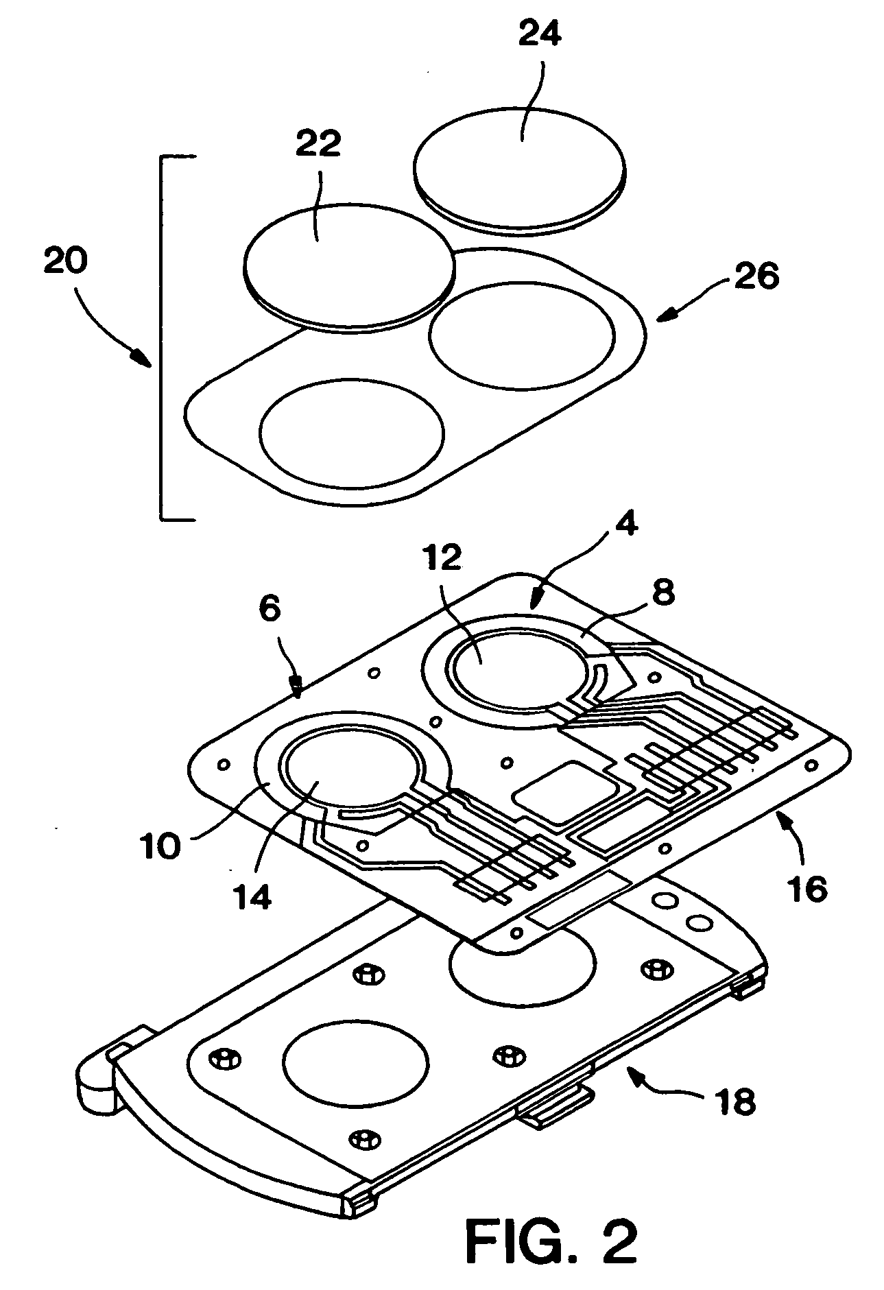
[0014] In a preferred embodiment, an automated system for iontophoretic extraction of analytes is provided, wherein iontophoretic electrodes capable of continual cycling under iontophoretic conditions are used to transdermally extract analytes continually over a period of about 1-24 hours, or longer. Therefore, unlike most iontophoresis applications, the iontophoretic electrodes of the invention are capable of passing current in both directions without concomitantly participating in undesirable side reactions, particularly water hydrolysis. In addition, the electrodes must have the capacity to pass a high amount of charge, which capacity is readily reversible so that the electrodes pass current reproducibly for an extended period of operation.
[0015] In another embodiment, an automated system for continual transdermal extraction of analytes present in biological fluids is provided, wherein the transdermal extraction is carried out using sonophoresis to extract analytes across a subject's skin. In this embodiment, a collection reservoir is contacted with a subject's skin. The reservoir contains a conductive medium, and is in contact with a sampling means for applying ultrasound to the contacted skin surface such that noninvasive sampling of analytes beneath the skin surface can be carried out. A biosensor is also in contact with the reservoir, providing a means for sensing and / or quantifying the concentration of a target analyte extracted into the reservoir.

Problems solved by technology

For example, the noninvasive nature of the sampling system significantly increases the likelihood of patient acceptance.
Again in the context of blood glucose monitoring, it is now believed that even four to seven glucose measurements per day may be insufficient to reflect the diurnal glucose level variation in many diabetics.

Method used


Image

  • Biosensor and methods of use thereof
  • Biosensor and methods of use thereof
  • Biosensor and methods of use thereof

Examples


example 1

Assessing Background Noise and Sensitivity in a Biosensor

[0111] The following procedure can be used to determine the background current and sensitivity to hydrogen peroxide of a biosensor electrode in a glucose monitoring system.

[0112] Method: The sensitivity and background of the working biosensor electrode is determined by placing the biosensor in a test cell of fixed volume. The cell is filled with a pH 7.5 0.1 M phosphate buffered saline (PBS) solution containing 77 mM NaCl. The buffer solution is quiescent in the cell during measurement. The biosensor is then biased at the usual operating potential of 0.6V, and the steady-state background current measured. A 2 μM solution of hydrogen peroxide is then prepared in the same PBS buffer solution, and is added to the test cell. The biosensor is again biased, and the-current measured at fixed time points. The measurement is repeated for 5 μM and 10 μM hydrogen peroxide solutions.

[0113] A calibration curve can be constructed from th...

example 2

Assessing Passive Hydrogen Peroxide Depletion in a Biosensor

[0117] The following procedure can be used to determine the rate of passive (non-electrochemical) hydrogen peroxide depletion caused by a biosensor electrode constructed in accordance with the present invention.

[0118] Method: The following procedure is optimized to test biosensor electrodes having an approximate geometric area of 1 cm2, and a total biosensor area of about 3 cm2; however, these methods are readily scalable to smaller or larger electrode dimensions by the ordinarily skilled artisan.

[0119] The biosensor to be tested is placed in a test cell which contains a volume of test solution of approximately 360 μL in contact with the electrode. The thickness of the solution layer in contact with the biosensor electrode is approximately 50 mil (0.127 cm). The body of the test cell is preferably made from materials that do not cause a substantial amount of hydrogen peroxide degradation, for example polytetrafluoroethyl...

example 3

Testing Protocol for Ag / AgCl Screen-Printed Electrodes

[0121] The following procedure can be used determine the amount of Ag and AgCl in a screen printed Ag / AgCl electrode that is electrochemically accessible at a given current density.

[0122] Method: The amount of available Ag and AgCl is determined by passing a constant current between the Ag / AgCl electrode and a counter electrode immersed in a suitable electrolyte until an increase in the applied voltage indicates that depletion of Ag or AgCl has occurred.

[0123] Test of available Ag: The Ag / AgCl electrode and a much larger counter electrode of chloridized silver foil are placed opposite each other in a beaker. The beaker is filled with 0.1 M PBS buffer (pH 7.5) containing 77 mM NaCl. The electrodes are connected to a suitable constant current power source and the electrodes biased so that the Ag / AgCl electrode is positive with respect to the counter electrode. A constant current passes between the electrodes. The applied potenti...


PUM

PropertyMeasurementUnit
Currentaaaaaaaaaa
Currentaaaaaaaaaa
Currentaaaaaaaaaa

Abstract

An automated system for continual transdermal extraction of analytes present in a biological system is provided. The system can be used for detecting and / or measuring the concentration of the analyte using an electrochemical biosensor detection means. The system optionally uses reverse iontophoresis to carry out the continual transdermal extraction of the analytes.

Description

CROSS-REFERENCE TO RELATED APPLICATIONS [0001] This application is a continuation-in-part of U.S. patent application Ser. No. 09 / 174,902, filed 19 Oct. 1998, from which priority is claimed under 35 USC §120, which is related to U.S. provisional patent applications Ser. Nos. 60 / 077,993, filed Mar. 13, 1998, and 60 / 080,591, filed Apr. 3, 1998, from which priority is claimed under 35 USC §119(e)(1), and which applications are incorporated herein by reference in their entireties.TECHNICAL FIELD [0002] This invention relates generally to a biosensor for use in monitoring the concentration of target chemical analytes present in an aqueous biological system. More particularly, the invention relates to a biosensor for measuring the concentration of one or more analytes in a transdermally extracted sample. The invention also relates to an electrode system for continual transdermal extraction of one or more analytes from a biological system over an extended period of operation. One important ...

Claims


Application Information

Patent Timeline
IPC IPC(8): A61B5/00A61B5/0408A61B5/145A61B5/1477A61N1/30G01N27/28G01N27/30G01N27/416G01N33/487G01N33/66
CPCA61B5/14514A61B5/14532A61N1/30A61B5/1495A61B5/1486C12Q1/26
Inventor BERNER, BRETKIM, LYNNPARRIS, NORMAN A.POTTS, RUSSELL O.TAMADA, JANETTIERNEY, MICHAEL J.
Owner ANIMAS TECH
Learn More