Energy filter device

Inactive Publication Date: 2005-02-10
GSI HELMHOLTZZENT FUR SCHWERIONENFORSCHUNG
View PDF9 Cites 20 Cited by
  • Summary
  • Abstract
  • Description
  • Claims
  • Application Information

AI Technical Summary

Benefits of technology

The object of the invention is thus to provide an energy filter device by means of which the energy spectrum of laser-induced beams

Problems solved by technology

However, it has been found that the laser-induced radiation has an energy spectrum which is very poor for cancer therapy, and thus a poor depth dose profile.
However, in th

Method used


Image

  • Energy filter device
  • Energy filter device
  • Energy filter device

Examples


Embodiment Construction

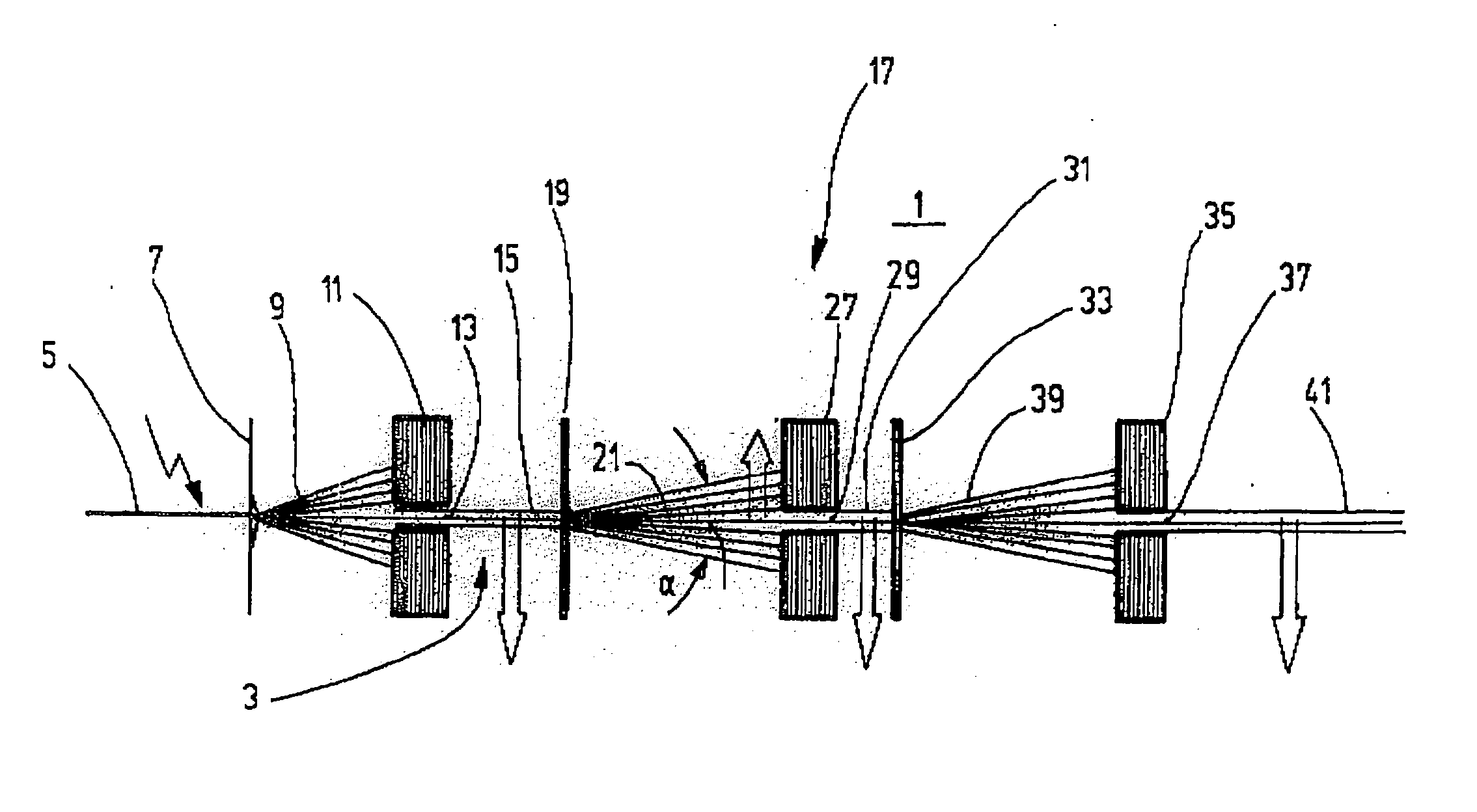
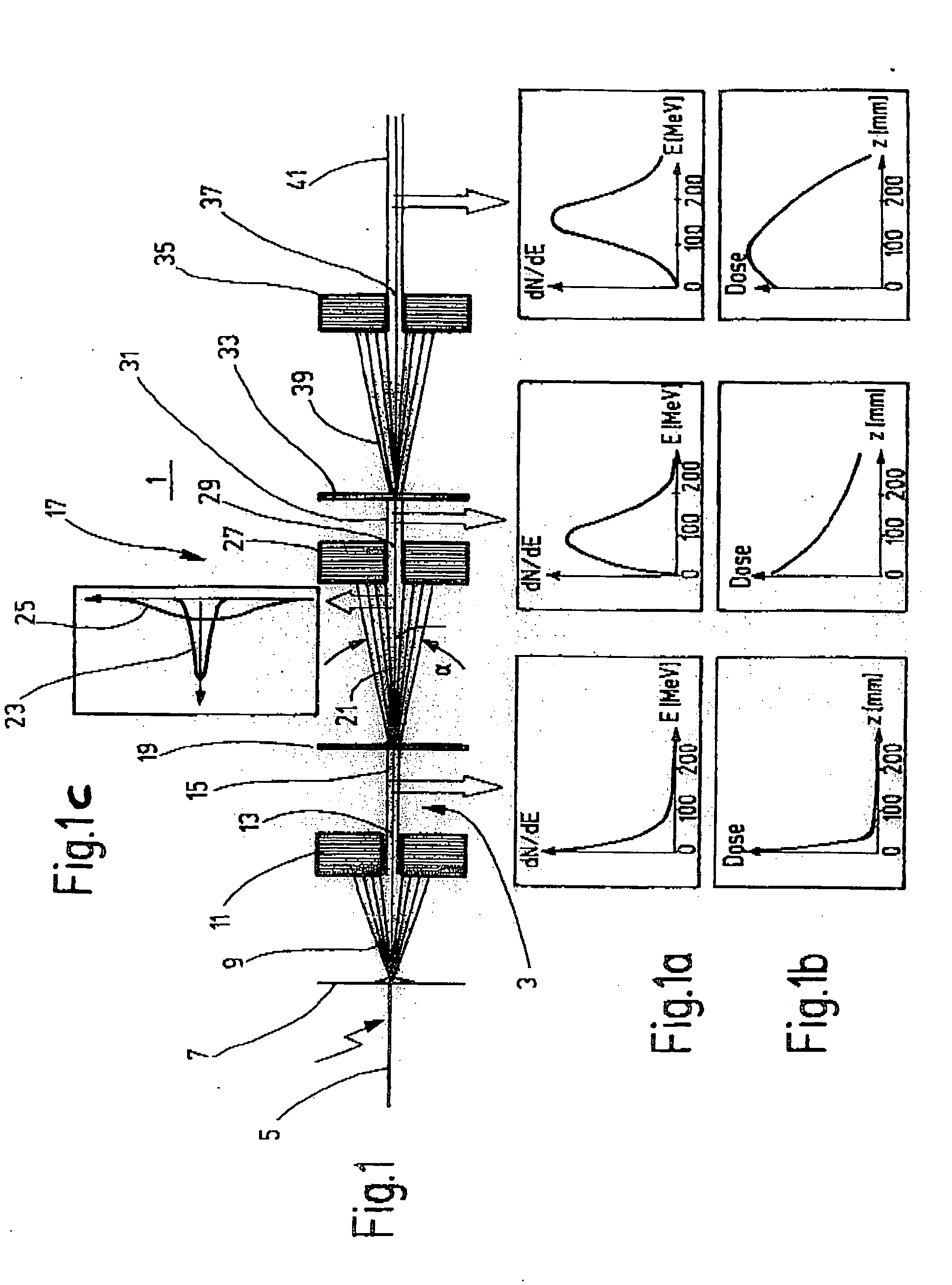
FIG. 1 shows an ion beam energy filter device, which will be referred to in the following text for short as an energy filter device 1, and through which an ion beam 3 passes. This ion beam 3 is produced by a high-intensity, pulsed laser beam 5, which strikes a target, in this case a converter film 7. Heavy charged particles 9, protons and relatively heavy ions are deposited on this converter film 7. The energy spectrum of the ion radiation made up of these particles 9 cannot be used in practice for radiation therapy, nor can the range profile associated with it.

A first collimator 11 which has a collimator opening 13 is arranged at a distance from the converter film 7, with a collimated beam 15 with a broad spectrum and a strong low-frequency component emerging through this collimator opening 13. The outer part of the radiation is masked out by the collimator 11.

The energy spectrum of the beam 15 is shown underneath it, in schematic form, in FIG. 1a. Underneath this, FIG. 1b shows...


PUM


Abstract

An energy filter device for beams which are used in the course of ion beam therapy, wherein at least one passive modulator is provided. The modulator comprises a scattering film for the beams and a collimator with an opening for controlling the beams.

Description

BACKGROUND OF THE INVENTION The invention relates to an energy filter device for beams used in low beam therapy for controlling the beam intensity and the dose strength of the beam. Ion beams, that is beams of protons and heavier ions, are used for beam therapy for tumor tissues. Beams of this type have the advantage over photons that they have a considerably better depth dose profile. While, in the case of photon radiation, the dose decreases as the penetration depth increases, it rises slowly in the case of ions and falls away steeply after a sharp maximum, the so-called Bragg peak. The position of this maximum must be distributed accurately over the target volume, in order to concentrate the dose on the tumor and at the same time to reduce the integral dose in the healthy tissue. This also applies to the laser-induced ion beams. Recently, it has been shown that high-intensity, pulsed laser beams can be used to produce relatively tightly focused proton beams from films. However,...

Claims


Application Information

Patent Timeline
IPC IPC(8): A61N5/10G21K1/04G21K1/10
CPCA61N5/1042A61N2005/1087G21K1/10G21K1/04G21K1/046A61N2005/1095
Inventor KRAFT, GERHARDWEBER, ULRICHKRAFT, SEBASTIANKRAFT, STEPHAN
Owner GSI HELMHOLTZZENT FUR SCHWERIONENFORSCHUNG
Why Eureka
Try Eureka