Emissive flat panel display device
a flat panel display and emissive technology, applied in the field of display devices, can solve the problems of coarse display screen and non-uniform display, and achieve the effect of increasing the density of emission sites
- Summary
- Abstract
- Description
- Claims
- Application Information
AI Technical Summary
Benefits of technology
Problems solved by technology
Method used
Image
Examples
first embodiment
[0065] Next, the detailed structure of the back panel is explained in conjunction with FIG. 15 to FIG. 17. FIG. 15 is a plan view for schematically explaining the structure of an essential part of the back panel and shows a portion where the pixels are provided in a 2×2 array. FIG. 16 is a cross-sectional view taken along a line A-A′ in FIG. 15 and FIG. 17 is a cross-sectional view taken along a line B-B′ in FIG. 15. In FIG. 15 to FIG. 17, on a surface of the back substrate 909 (corresponding to reference numeral 601 in FIG. 11 and FIG. 12) made of glass, 600 stripe-like cathode electrodes 901 (corresponding to reference numeral 701 in FIG. 11 and FIG. 12) having a thickness of 0.2 to 10 μm and a width of 300 μm are formed at an interval of 60 μm. Next, an insulation layer 905 is formed in a state that the insulation layer 905 covers the cathode electrodes 901. A thickness of the insulation layer 905 is set to 1 to 50 μm. In the pixel portion of the insulation layer, that is, in the...
second embodiment
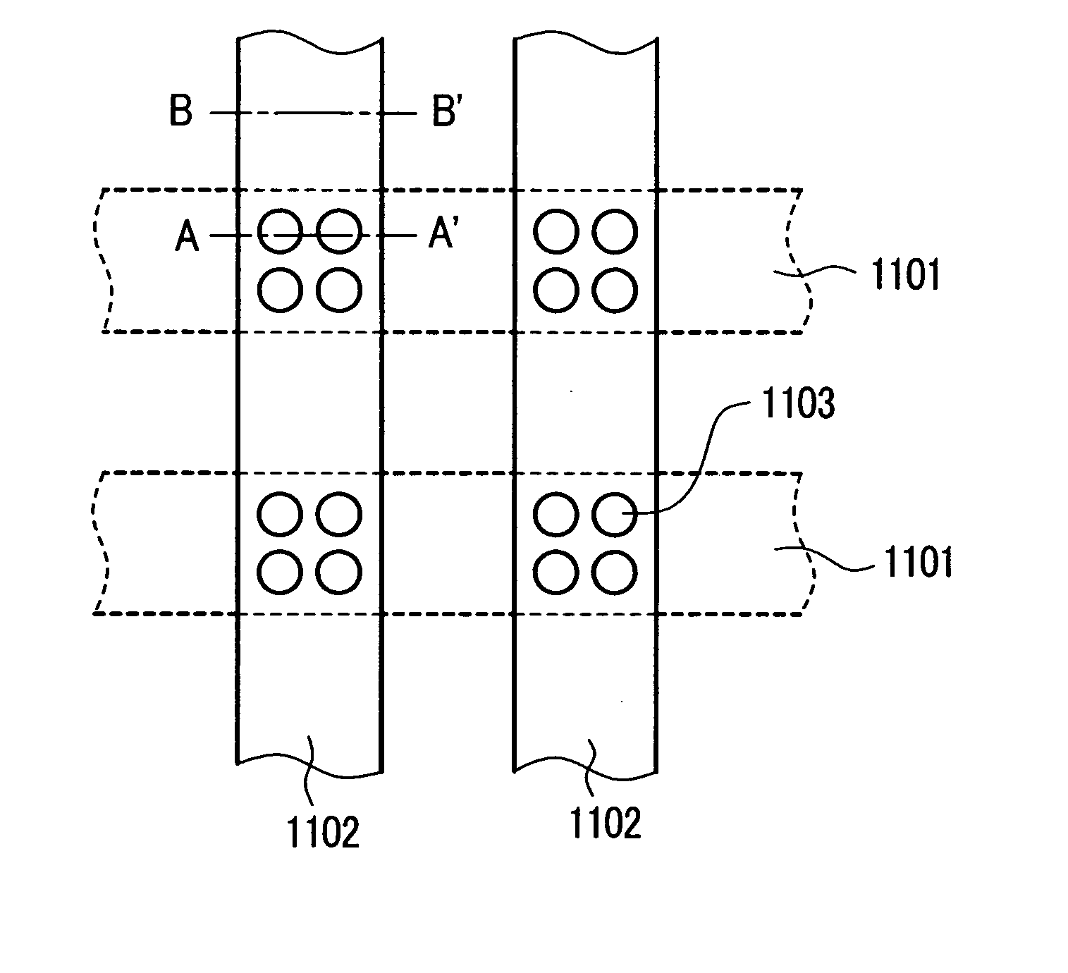
[0075] Next, the detailed structure of the back panel is explained in conjunction with FIG. 22 to FIG. 24. FIG. 22 is a plan view for schematically explaining the structure of an essential part of the back panel of the emissive flat panel display device of the present invention and shows a portion where the pixels are provided in a 2×2 array. FIG. 23 is a cross-sectional view taken along a line A-A′ in FIG. 22 and FIG. 24 is a cross-sectional view taken along a line B-B′ in FIG. 22. In FIG. 22 to FIG. 24, on a surface of the back substrate 1109 (corresponding to reference numeral 601 in FIG. 11 and FIG. 12) preferably made of glass, 600 cathode electrodes 1101 (corresponding to reference numeral 901 in FIG. 15 to FIG. 17) having a thickness of 0.2 to 10 μm and a width of 300 μm are formed at an interval of 60 μm. Next, an insulation layer 1105 is formed in a state that the insulation layer 1105 (corresponding to reference numeral 905 in FIG. 15 to FIG. 17) covers the cathode electro...
PUM
 Abstract
Description
Claims
Application Information
 - R&D
- Intellectual Property
- Life Sciences
- Materials
- Tech Scout
- Unparalleled Data Quality
- Higher Quality Content
- 60% Fewer Hallucinations
Browse by: Latest US Patents, China's latest patents, Technical Efficacy Thesaurus, Application Domain, Technology Topic, Popular Technical Reports.
© 2025 PatSnap. All rights reserved.Legal|Privacy policy|Modern Slavery Act Transparency Statement|Sitemap|About US| Contact US: help@patsnap.com


