Apparatus for active cooling of an MRI patient bore in cylindrical MRI systems

a technology of active cooling and patient bore, which is applied in the field of active cooling of mri patient bore, can solve problems such as patient discomfort, and achieve the effect of reducing the heat load in the patient bore and increasing patient comfor

Inactive Publication Date: 2005-02-10
GE MEDICAL SYST GLOBAL TECH CO LLC
View PDF11 Cites 85 Cited by
  • Summary
  • Abstract
  • Description
  • Claims
  • Application Information

AI Technical Summary

Benefits of technology

[0007] RF coils create the B1 field which rotates the net magnetization in a pulse sequence. They also detect the transverse magnetization as it precesses in the XY plane. In order to create the B1 field, current is then passed though the RF coil to generate a magnetic field. The resistive heating cau...

Problems solved by technology

The resistive heating caused by large current flow caus...

Method used


Image

  • Apparatus for active cooling of an MRI patient bore in cylindrical MRI systems
  • Apparatus for active cooling of an MRI patient bore in cylindrical MRI systems
  • Apparatus for active cooling of an MRI patient bore in cylindrical MRI systems

Examples


Embodiment Construction

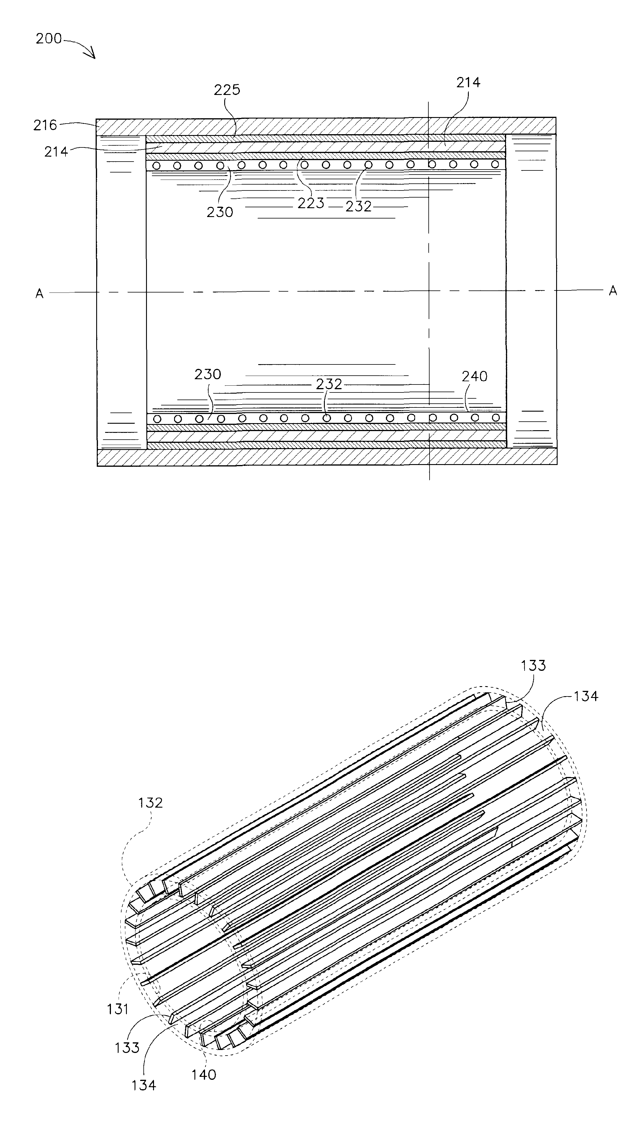
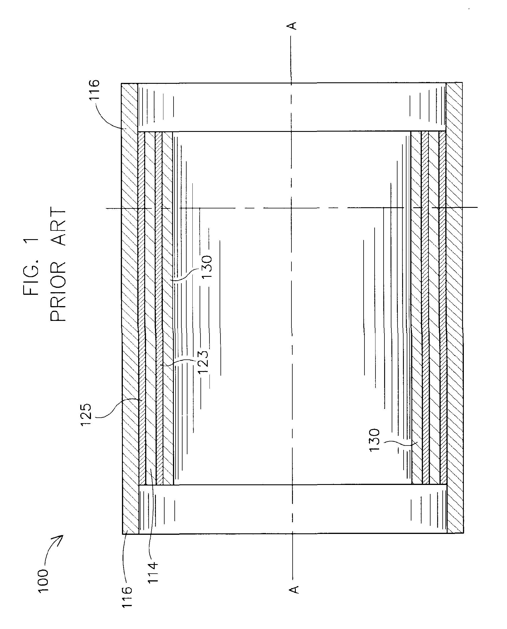
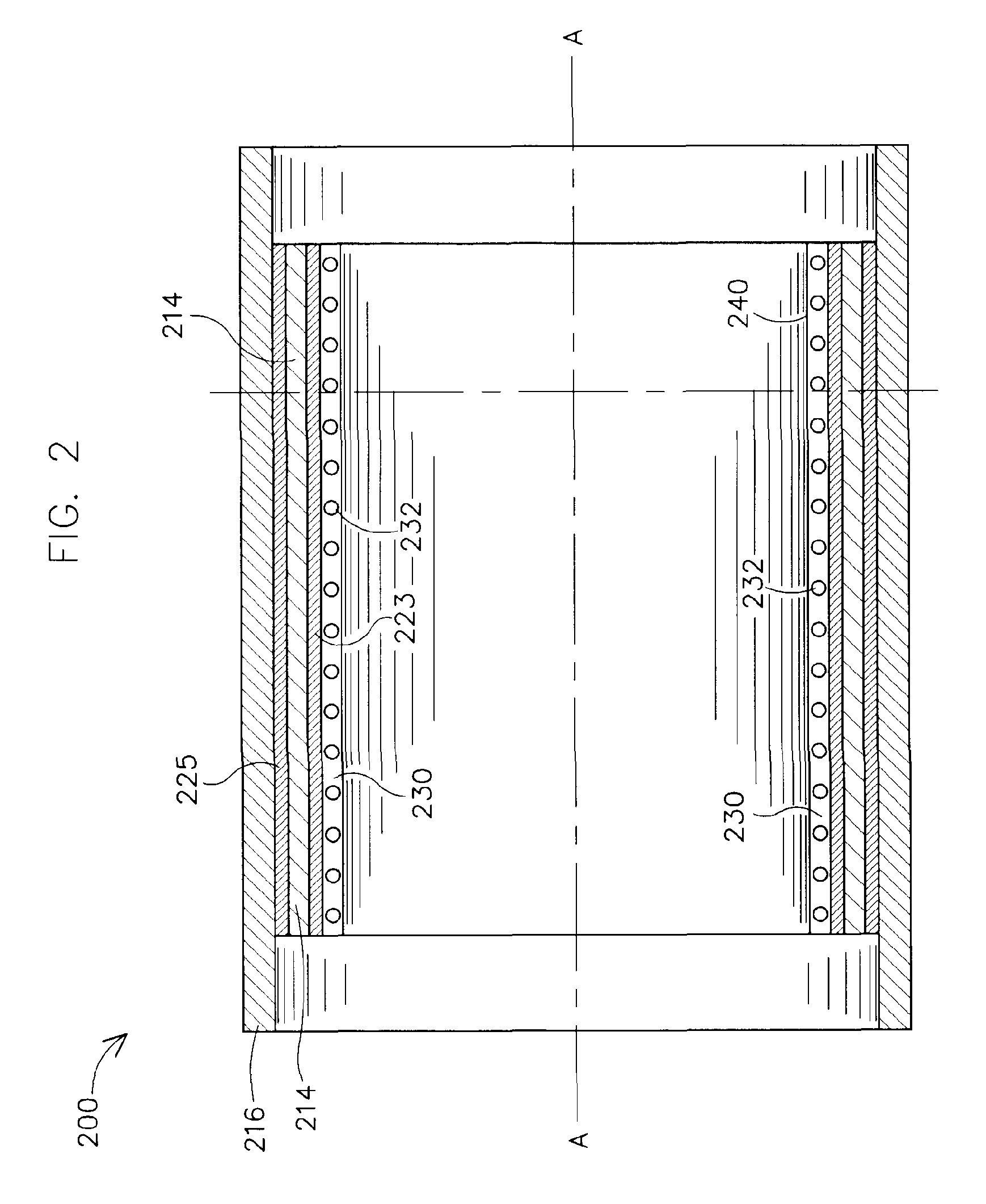
[0019] Referring now to the drawings in detail, wherein like numbered elements correspond to like elements throughout, FIG.1 shows that portion of an MRI imaging system 100 comprising an RF coil 130, gradient coil 114, magnet 116 and patient bore surface of the prior art. Also shown in FIG. 1 is a dual layer of an epoxy-like material 123, 125, used to separate the conductive layers. FIG. 2 shows that portion of an MRI imaging system 200 comprising a magnet 216, gradient coil 214, patient bore surface 240 and RF magnet coil 230 for the MR imaging system of the present invention. Referring more specifically to the drawings, FIG. 2 shows a MRI assembly 200 for an MR imaging system (not shown), comprising an MR magnet 216, cylindrical gradient coil windings 214, and an RF coil 230 respectively, disposed in concentric arrangement with respect to common access A. Generally, continuous cooling tubes are wound in a helix through the gradient coil winding 214. The gradient coil windings 214 ...


PUM


Abstract

The present invention provides for a cooling system for circulating a coolant to cool the patient bore. In one embodiment, that patient bore consists of two concentric cylinders separated by spacers running either longitudinally or helically. In another embodiment of the present invention, fluid may be passed either helically or longitudinally through tubes bonded to the outer diameter of the patient bore such that the parts of the bore that are exposed to the patient are directly cooled. In a third embodiment, the RF coil could form part of the patient bore, with the helical or longitudinal fluid channels surrounding the patient bore.

Description

BACKGROUND OF INVENTION [0001] The present invention relates generally to magnetic resonance imaging (MRI) systems, and more particularly to an assembly designed to dissipate the heat generated by the gradient coils and RF coils that are used in MRI. [0002] When a substance such as human tissue is subjected to a uniform magnetic field (polarizing field B0), the individual magnetic moments of the spins in the tissue attempt to align with the polarizing field, but precess about it in random order at their characteristic Larmor frequency. If the substance, or tissue, is subjected to a magnetic field (excitation field B1) which is in the x-y plane and which is near the Larmor frequency, the net aligned moment, or “longitudinal magnetization”, Mz may be rotated, or “tipped”, into the x-y plane to produce a net transverse magnetic movement Mt. A signal is emitted by the excited spins after the excitation signal B1 is terminated and this signal may be received and processed to form an imag...

Claims


Application Information

Patent Timeline
IPC IPC(8): A61B5/055G01R33/34G01R33/28G01R33/38H01F7/20H01F27/10H01F27/32
CPCG01R33/3403G01R33/34046H01F27/322H01F7/202H01F27/10G01R33/3804G01R33/34
Inventor CLARKE, NEILSELLERS, MICHAEL B.ALLFORD, MICHAEL L.MANTONE, ANTHONY
Owner GE MEDICAL SYST GLOBAL TECH CO LLC
Why Eureka
Try Eureka