
Atomic layer deposition of CMOS gates with variable work functions

Inactive Publication Date: 2005-02-10
ROUND ROCK RES LLC
View PDF99 Cites 116 Cited by
  • Summary
  • Abstract
  • Description
  • Claims
  • Application Information

AI Technical Summary

Benefits of technology

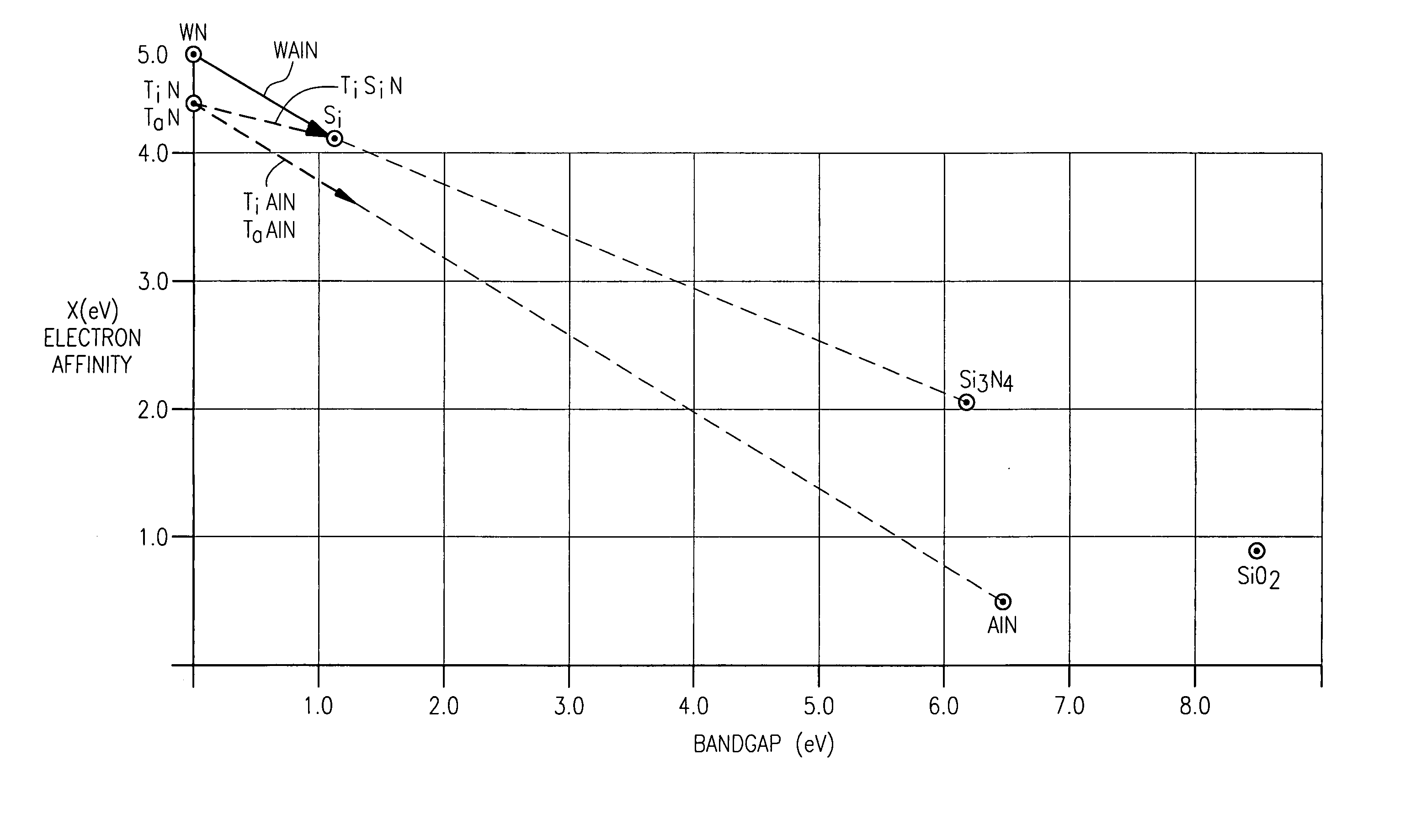
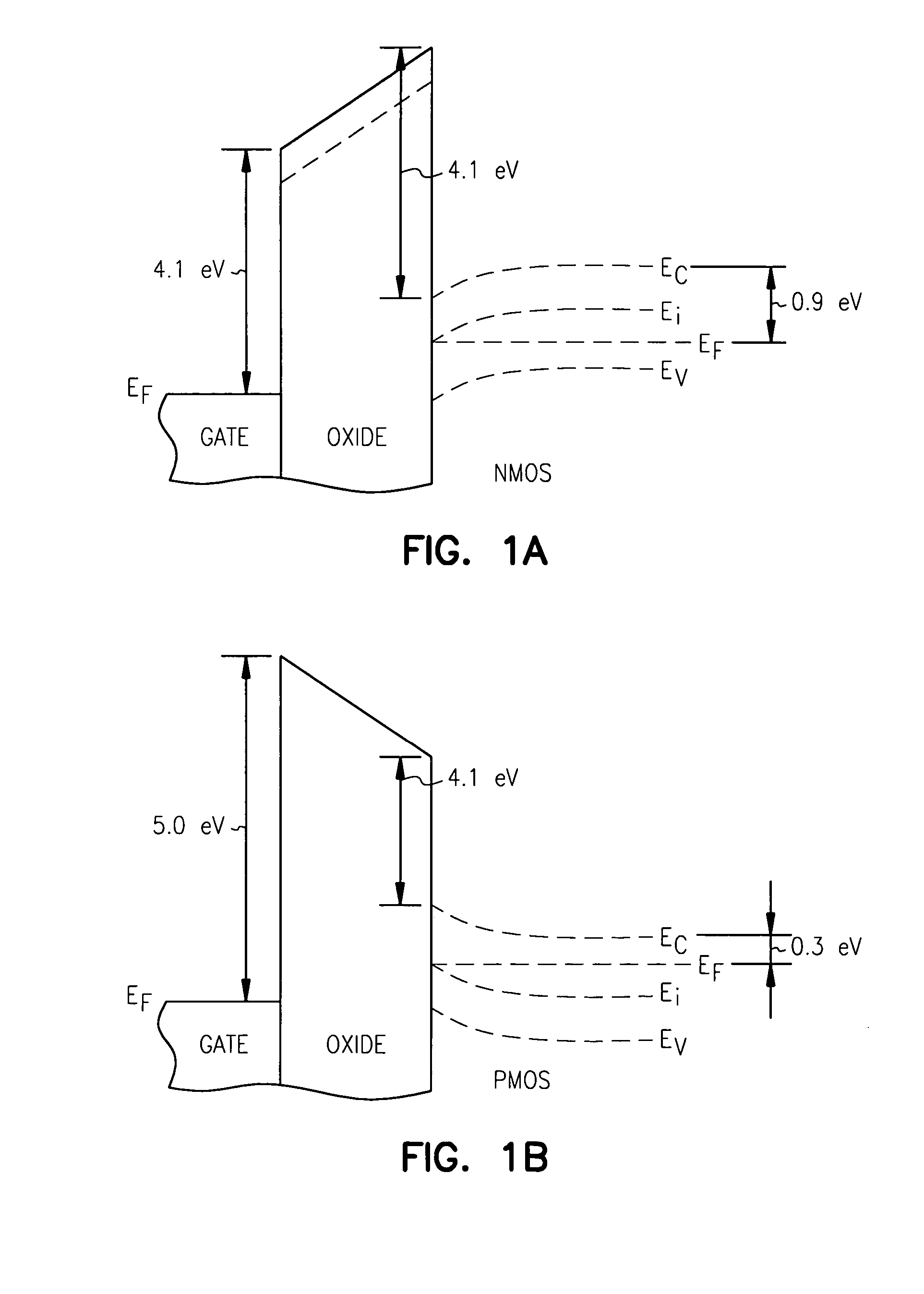
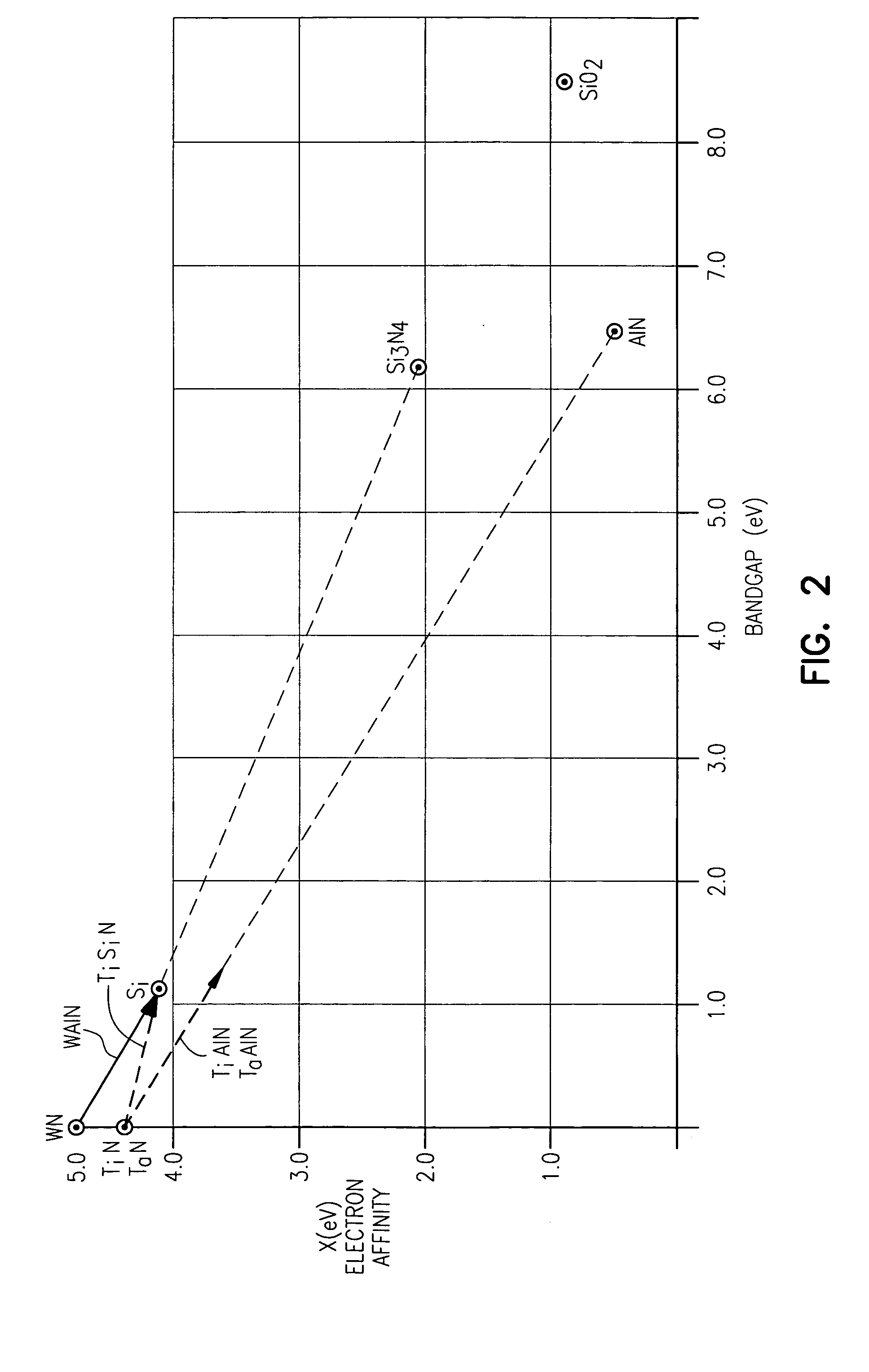
[0010] The above mentioned problems CMOS transistor design as well as other problems are addressed by the present invention and will be understood by reading and studying the following specification. This disclosure describes the use of atomic layer deposition of ternary metallic conductors where the composition and work function are varied to control the threshold voltage of both the NMOS and PMOS transistors in CMOS technology to provide optimum performance.

Problems solved by technology

Conventional n-type doped polysilicon gate electrodes in CMOS technology have two problems.
Firstly, the polysilicon is conductive but there can still be a surface region which can be depleted of carriers under bias conditions.
While this region is thin, in the order of a few angstroms (Å), it becomes appreciable as gate oxide thicknesses are reduced below 2 nm or 20 Å. Another problem is that the work function is not optimum for both n-MOS and p-MOS devices, historically this was compensated for by threshold voltage adjustment implantations.
However, as the devices become smaller, with channel lengths of less than 1000 Å and consequently surface space charge regions of less than 100 Å, it becomes more and more difficult to do these implantations.
However, these were deposited by physical deposition not atomic layer deposition and only capacitor structures were fabricated, not transistors with gate structures.

Method used


Image

  • Atomic layer deposition of CMOS gates with variable work functions
  • Atomic layer deposition of CMOS gates with variable work functions
  • Atomic layer deposition of CMOS gates with variable work functions

Examples


Embodiment Construction

[0018] In the following detailed description of the invention, reference is made to the accompanying drawings which form a part hereof, and in which is shown, by way of illustration, specific embodiments in which the invention may be practiced. In the drawings, like numerals describe substantially similar components throughout the several views. These embodiments are described in sufficient detail to enable those skilled in the art to practice the invention. Other embodiments may be utilized and structural, logical, and electrical changes may be made without departing from the scope of the present invention.

[0019] The terms wafer and substrate used in the following description include any structure having an exposed surface with which to form the integrated circuit (IC) structure of the invention. The term substrate is understood to include semiconductor wafers. The term substrate is also used to refer to semiconductor structures during processing, and may include other layers that...


PUM


Abstract

Structures, systems and methods for transistors having gates with variable work functions formed by atomic layer deposition are provided. One transistor embodiment includes a first source / drain region, a second source / drain region, and a channel region therebetween. A gate is separated from the channel region by a gate insulator. The gate includes a ternary metallic conductor formed by atomic layer deposition.

Description

CROSS REFERENCE TO RELATED APPLICATION [0001] This application is a Divisional of U.S. Ser. No. 10 / 225,605 filed on Aug. 22, 2002, which application is incorporated herein by reference.FIELD OF THE INVENTION [0002] The present invention relates generally to semiconductor integrated circuits and, more particularly, to atomic layer deposition of CMOS gates with variable work functions. BACKGROUND OF THE INVENTION [0003] Conventional n-type doped polysilicon gate electrodes in CMOS technology have two problems. Firstly, the polysilicon is conductive but there can still be a surface region which can be depleted of carriers under bias conditions. This appears as an extra gate insulator thickness and is commonly referred to as gate depletion and contributes to the equivalent oxide thickness. While this region is thin, in the order of a few angstroms (Å), it becomes appreciable as gate oxide thicknesses are reduced below 2 nm or 20 Å. Another problem is that the work function is not optimu...

Claims


Application Information

Patent Timeline
IPC IPC(8): H01L21/28H01L21/285H01L21/8238H01L27/092H01L27/10H01L29/423H01L29/49H01L29/78
CPCH01L21/28088H01L29/4966H01L21/823828H01L21/28562
Inventor FORBES, LEONARDAHN, KIE Y.
Owner ROUND ROCK RES LLC
Learn More