
Air-conditioning system for a motor vehicle

a technology for air-conditioning systems and motor vehicles, which is applied in the direction of machine operation, compression machines with several condensers, light and heating apparatus, etc. it can solve the problems of cabin air not being heated directly, documenting the problem of windows fogging up in the cabin of the vehicle, and high system inertia, so as to reduce fuel consumption and pollutant emissions, reach the operating temperature quickly, and reduce active liquid volume

Inactive Publication Date: 2005-02-17
HANON SYST
View PDF19 Cites 28 Cited by
  • Summary
  • Abstract
  • Description
  • Claims
  • Application Information

AI Technical Summary

Benefits of technology

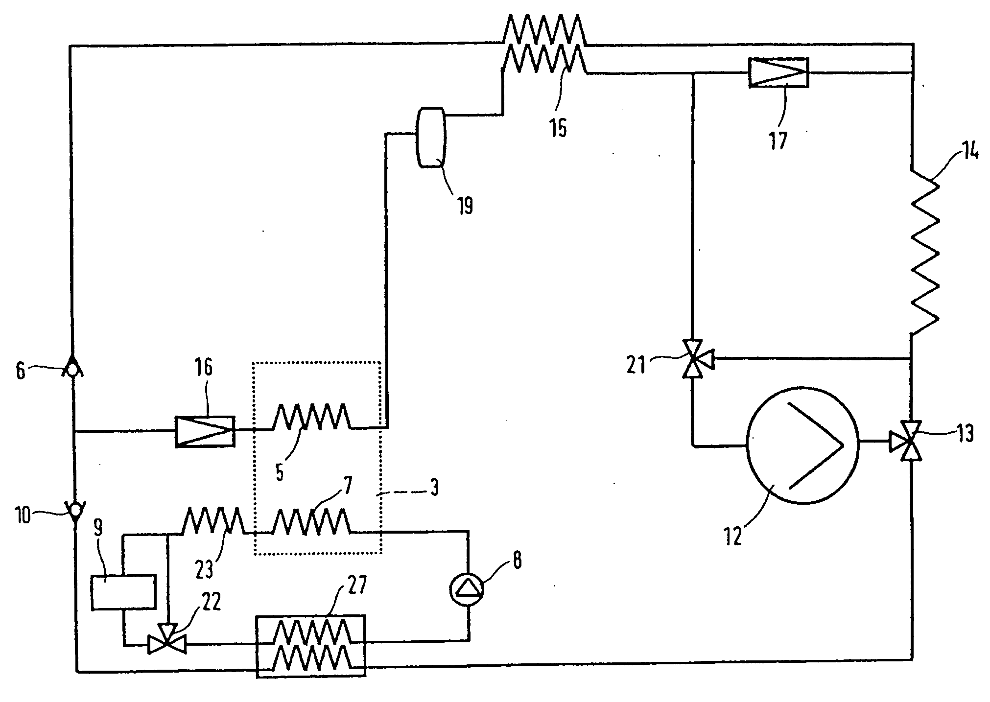
[0025] When the heat pump is operating for heating purposes, two operating situations may arise: heating and drying or heating. In the first case, the compressed refrigerant is condensed / cooled in the heat pump condenser. In the process, it releases its heat directly to the cabin air or introduces it indirectly into the heating-agent stream upstream of the heating heat exchanger. The refrigerant then reaches a controllable expansion valve, in which it is controlled to a temperature which is sufficient for drying of the air and is as far as possible comfortable. Then, the refrigerant is expanded to a temperature below that of the heat source. Here, the refrigeration circuit takes up heat. In the heating operating mode, the compressed refrigerant is condensed / cooled in the heat pump condenser. In the process, it releases its heat directly to the cabin air or introduces it indirectly into the heating-agent stream upstream of the heating heat exchanger. The refrigerant then reaches the fully open first expansion valve, in which the refrigerant is only slightly throttled, and the refrigerant can be further cooled. The incoming cabin air is preheated. This makes it possible to further increase the heating capacity of the installation. Then, the refrigerant is expanded to a temperature below that of the heat source. In the process, the refrigeration circuit takes up heat and the refrigerant is returned to the refrigerant compressor.
[0029] Furthermore, the invention includes, instead of the evaporator acted on directly by air and refrigerant in the air-conditioning unit, a heat-transfer liquid / air heat exchanger. Therefore, the transfer of heat to the interior compartment air takes place indirectly via a small active circuit of heat-transfer liquid. The heat-transfer liquid circuit comprises a liquid pump and a liquid / air heat exchanger. In addition, the heat-transfer liquid circuit may include a liquid storage vessel, which can increase the volume of liquid which is in circulation. Only a small volume of liquid circulates within this liquid circuit until the criteria for charging the storage vessel are satisfied. Then, a partial volume of the circulating liquid flows into the storage vessel until the storage vessel has adopted a desired or achievable temperature. This can be maintained during standard vehicle operation. If the capacity of the refrigeration installation then drops or if the refrigeration installation is switched off, it is possible for the temperature of the circulating heat-transfer liquid to be kept at a usable temperature level for a certain period of time by removing the heat-transfer liquid contained in the storage vessel.
[0032] By virtue of the invention, it is possible to use a heat pump installation for the cooling and drying and heating of the interior-compartment air for the vehicle cabin. It is possible to switch between the heating and cooling operating modes as desired without any adverse effect from window misting, in particular in winter. Furthermore, if necessary continuous drying of the interior compartment air is possible even when the heat pump is operating. The spontaneous response of the heat pump as heater means that the engine coolant is not required for heating purposes. Consequently, the engine reaches its operating temperature quickly. It is possible to reduce fuel consumption and pollutant emissions. If heat-transfer liquids are used to transport energy in order to cool and heat the interior compartment air, there are no components which carry refrigerant in the interior compartment or in the air stream to the vehicle cabin. This means that it is also possible to use, in vehicles, refrigerants which are advantageous for the particular application but are ruled out on account of combustibility or for toxicological reasons. If heat-transfer liquids are used, the active liquid volumes are small. After the vehicle has been started up, rapid heating or cooling of the interior compartment is possible. The circuit can be expanded by an additional storage volume. This maintains a high degree of thermal comfort even in the event of brief stops. After driving has been interrupted briefly, when the vehicle is started up a pre-conditioned storage volume with a corresponding heat capacity is available in order to rapidly implement conditioning of the interior compartment.
[0033] When the heat pump installation is used for cooling and heating, it is possible to employ either the heat, which is to be dissipated or the useful heat which has been made available, to heat various vehicle systems, such as the engine, transmission, differential transmission, etc. As a result, the fuel consumption drops considerably after a cold start, and component wear is considerably reduced. Furthermore, in the cooling mode, initially very large amounts of heat are withdrawn from the circuit, which in turn results in a high initial performance of the refrigeration installation, making it possible to achieve comfortable conditions in the interior compartment more quickly.

Problems solved by technology

This document does not solve the problem of the windows in the vehicle cabin fogging up when the refrigeration installation is switched from cooling and drying to heating.
One drawback of these solutions is that the cabin air is not heated directly, but rather by means of a heating heat exchanger in the heat-transfer medium circuit as part of the engine cooling system.
On account of the thermal masses involved, the inertia of the system is high, which has an adverse effect on the heating dynamics and is not compatible with traffic safety objectives.
A drawback of one solution is that, under certain frequent vehicle operating conditions such as previous drying of the air for the vehicle cabin at outside temperatures of, for example, 0° C. to 10° C., heating operation is not possible or only a very limited capacity can be obtained from the installation.
The other solution avoids the desirable continuous drying of air when utilizing the refrigeration installation in a heat pump mode and therefore does not comply with the requirements of keeping the windows in the vehicle cabin free of fogging, in particular in an air recirculation mode.
Dehumidification devices based for example on adsorptive materials cause a pressure drop in the air mass flow for the ventilation of the vehicle cabin and have to be desorbed periodically.
Drawbacks are that a high thermal load is constantly introduced into the air-conditioning unit, the heating heat exchanger has to withstand high temperature and pressure loading, the piping of the installation in the vehicle is complex and takes up a considerable amount of space, there are avoidable pressure drops with a reduction in efficiency and a substantial amount of refrigerant is required.
Therefore, the installation does not satisfy the general demands with regard to complexity, costs, efficiency, performance and ecological requirements.
This can lead to increased fogging of the windows.
When the heat exchanger through which refrigerant flows is being used for heating purposes, the function of cooling and therefore drying cannot be performed simultaneously.

Method used


Image

  • Air-conditioning system for a motor vehicle
  • Air-conditioning system for a motor vehicle
  • Air-conditioning system for a motor vehicle

Examples


Embodiment Construction

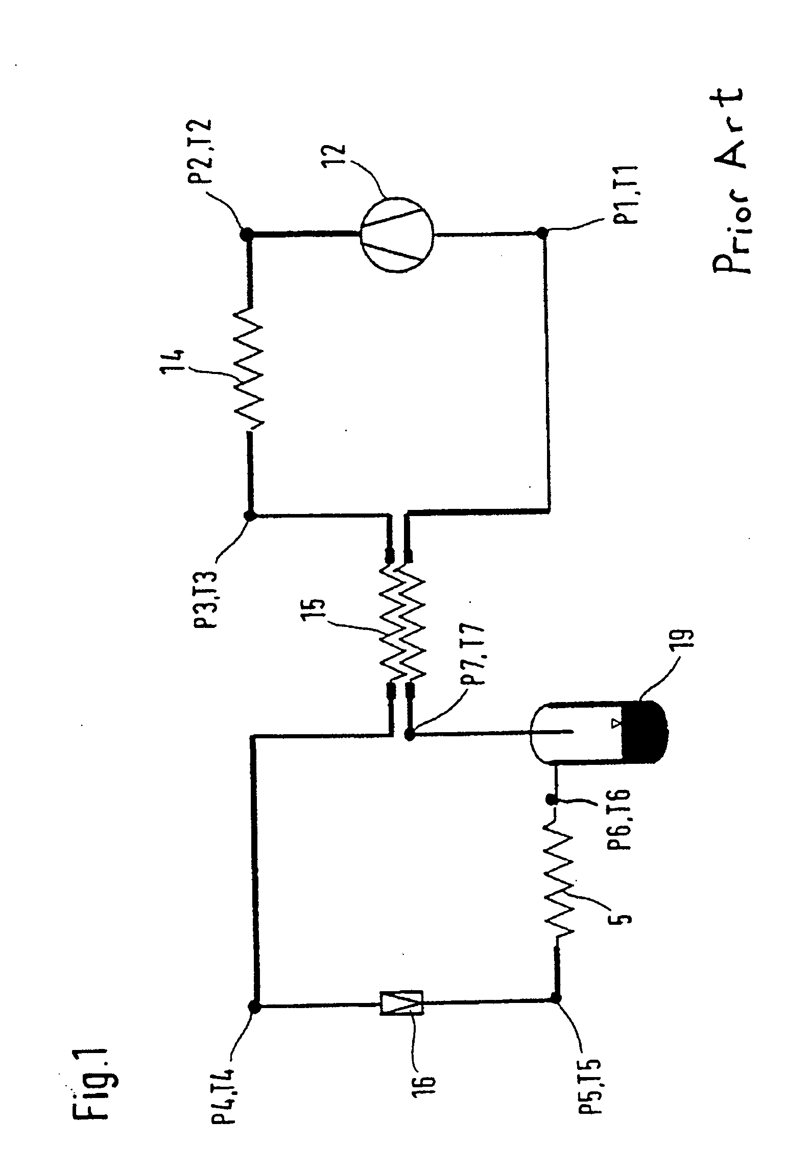
[0057]FIG. 1 shows a circuit which includes, connected in series one after the other, a compressor 12, a gas cooler / condenser 14, an internal heat exchanger 15, a throttling means 16, an evaporator 5 and a collector 19. The mass flow of refrigerant in the compressor is controllable. The throttling means 16, which may be an expansion valve, is likewise controllable.

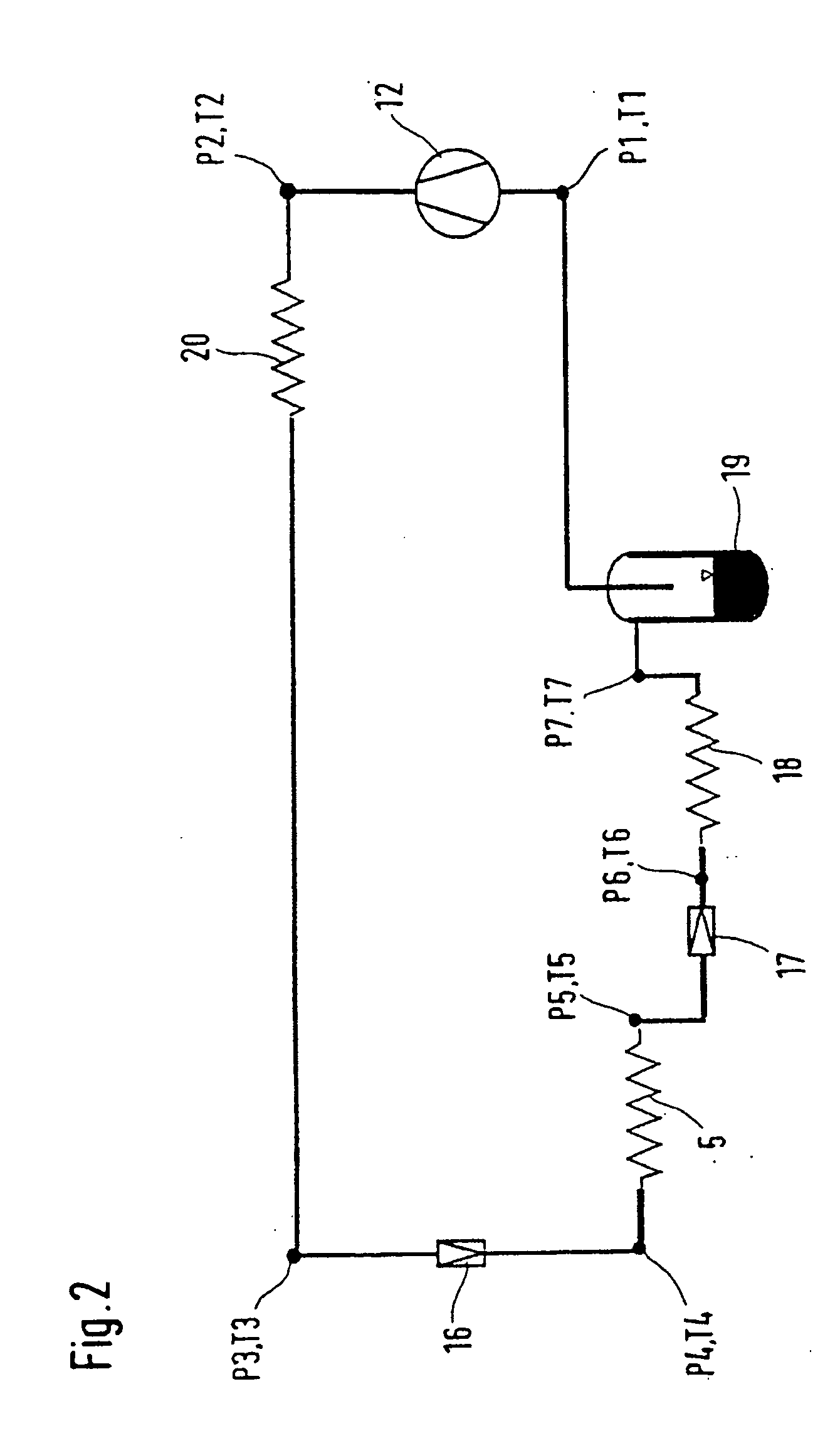
[0058]FIG. 2 shows a refrigeration circuit which is designed as a heat pump and includes, connected in series one after the other, a compressor 12, a gas cooler / condenser 20, a first throttling means 16, a first evaporator 5, a second throttling means 17, a second evaporator 18 and a collector 19. The mass flow of refrigerant in the compressor is controllable. The first throttling means 16 is also controllable, and the second throttling means 17 may be designed such that it can be shut off in a controllable and sealed manner. The second throttling means 17 may also be designed as a constant throttling element with an addi...


PUM


Abstract

In an air-conditioning system for a motor vehicle having an integrated heat pump for cooling and heating, in which refrigerant is circulated and which allows heat exchange with the incoming air for the interior compartment of the motor vehicle, the heat transfer is effected either directly, by means of a refrigerant / air heat exchanger through which the air for the interior compartment is conducted, or by means of a secondary refrigerant circuit, which includes two expansion devices and three heat exchangers provided in the refrigerant circuit of the system.

Description

[0001] This is a Continuation-In-Part Application of International Application PCT / EP02 / 13279 filed Nov. 26, 2002 and claiming the priority of German Application 201 21 533.0 filed Dec. 21, 2001.BACKGROUND OF THE INVENTION [0002] Air-conditioning equipment in vehicles form part of the prior art for the cooling, drying, heating and ventilation of vehicle interior compartments. The air is cooled and dried by means of refrigeration installations, while for heating purposes the cabin air is normally heated in heating heat exchangers which make the waste heat from the engine available. The cabin is ventilated by means of outside air or re-circulated air from the cabin via air blowers. Furthermore, the air-conditioning equipment is used to control the distribution of air in the cabin. [0003] Refrigeration installations for the air-conditioning of a cabin in vehicles are known for cooling / drying and heating purposes. In these installations, a pressure which is supercritical with respect to...

Claims


Application Information

Patent Timeline
IPC IPC(8): B60H1/32B60H1/00F25B5/00F25B6/04F25B9/00F25B29/00F25B40/00
CPCB60H1/00899B60H2001/00942B60H2001/00949B60H2001/00957F25B2600/2501F25B40/00F25B2309/061F25B2341/0662F25B9/008F25B41/39
Inventor CASAR, ROLANDGARTNER, JANGEIGER, STEFFENHARM, KLAUSWERTENBACH, JURGEN
Owner HANON SYST
Learn More