
Extended area filter

Inactive Publication Date: 2005-02-17
MOTT CORP
View PDF20 Cites 19 Cited by
  • Summary
  • Abstract
  • Description
  • Claims
  • Application Information

AI Technical Summary

Benefits of technology

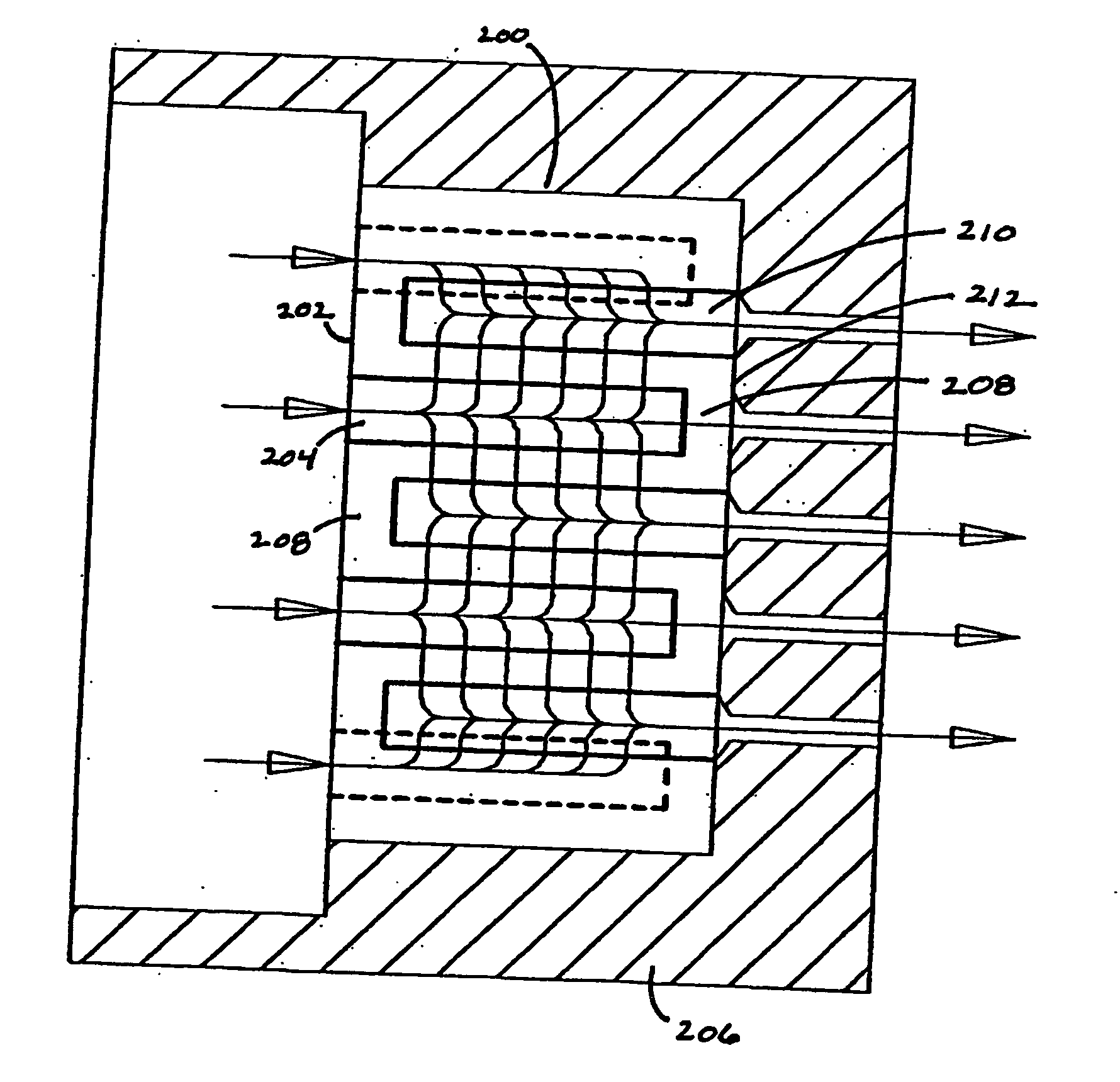
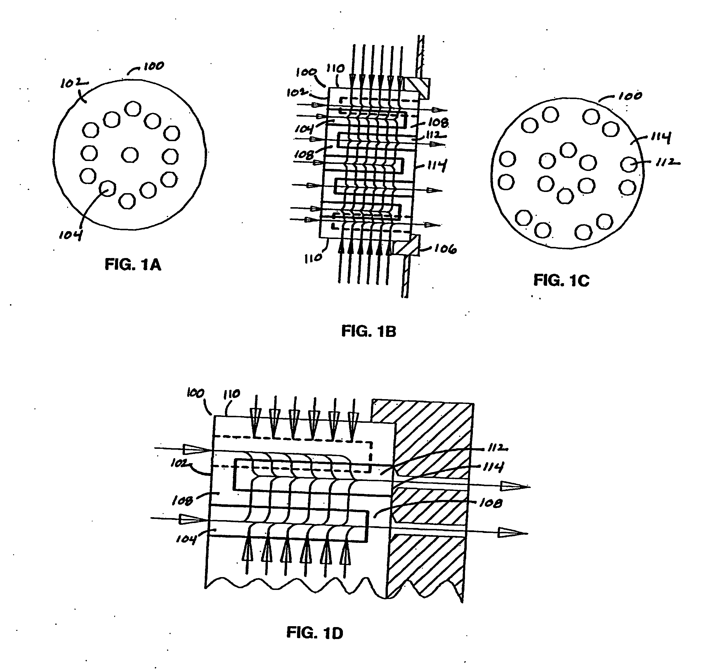
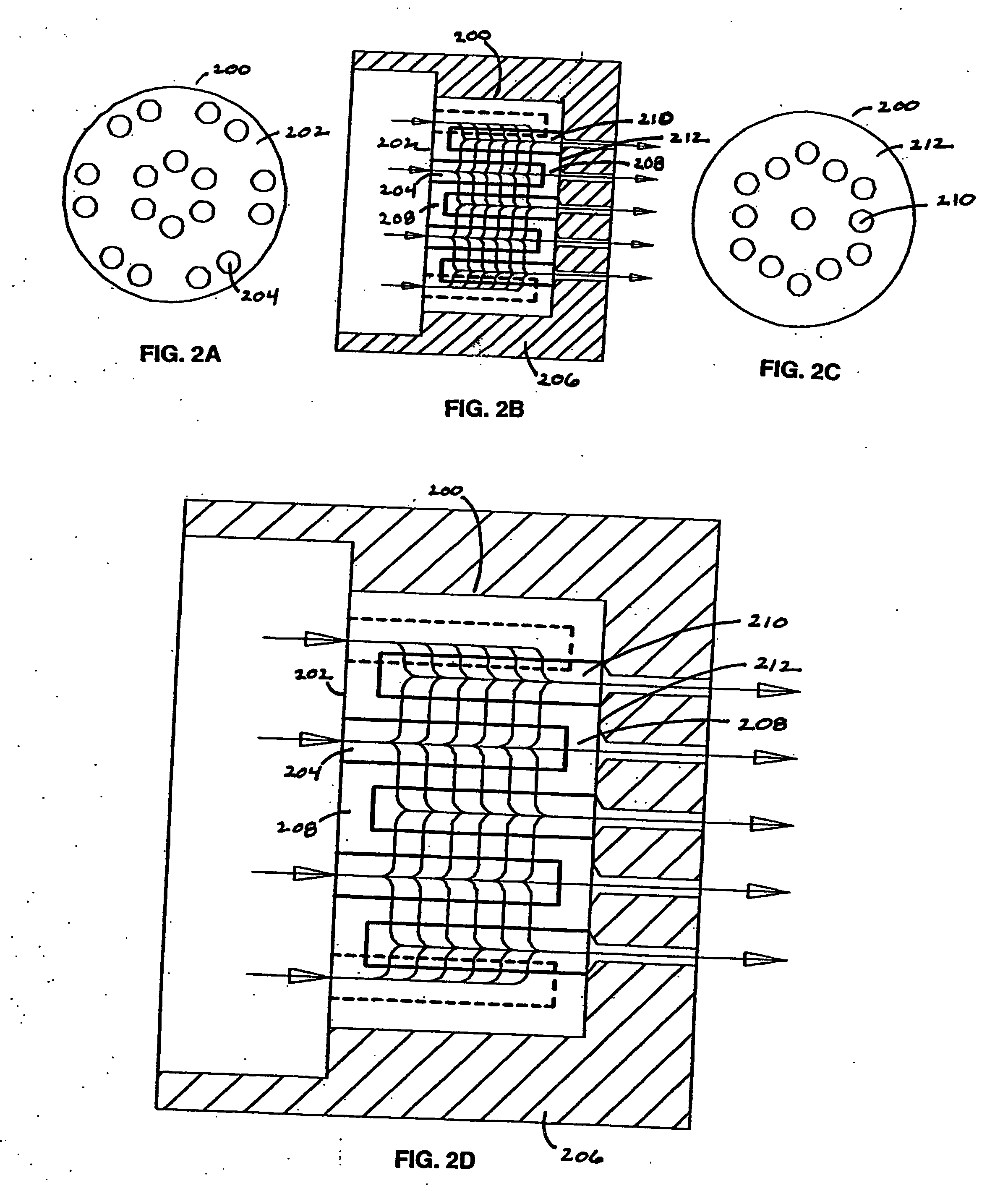
[0010] The invention provides an extended area filter that is particularly useful in polymer melt filtration. The filter offers improved uniformity of flow, increased throughput, and extended filtration life, and is efficiently and economically produced, installed, maintained, and replaced.

Problems solved by technology

Unless removed by filtration, such impurities can clog the spinnerette or pass through the spinnerette and cause defects in the product polymer fiber.
These layers create a depth filtration effect, which prolongs the life of the filter because larger contaminant particles are removed by the coarse upstream filtration layers, leaving the finer downstream filtration layers open to retain smaller contaminant particles.
However, loose media do not provide optimal filtration, as they tend to migrate, separate, channel, and fluidize.
Such irregular, uncontrollable motion of the particles of loose fill reduces filtration effectiveness and causes inconsistent filtration over the life of a filter and across filters.
Further, metal fiber has a large open void volume, which affords great dirt holding capacity but has limited ability to impart shear.
However, traditional porous metal filters often have difficulty withstanding the high pressures used in polymer melt extrusion or, if they are thick enough to withstand such pressures, afford sub-optimal flow rates.
Furthermore, porous metal discs and cups often suffer from reduced filtration life due to surface blinding and caking.
Such filters offer extended filtration area, but sometimes include a multi-component assembly (e.g., a group of cups in an adapter) that is subject to leakage between components.
Furthermore, many extended area filters require a thick inter-cavity wall structure to afford sufficient strength for high-pressure applications, which adversely affects flow rate and throughput.
Furthermore, the production of many extended area filters is time-consuming and expensive, and some commonly used production steps cause shortcomings in the end product.
For example, machining steps typically used to form the cavity structure of extended area filters often cause distortions in the pores and surface morphology of the filters, such as non-uniform density, smeared pores, and surface blinding.
Such structural distortions result in reduced flow rate and consistency, and decreased filtration life.
Another common production technique that causes drawbacks in the final filter product involves the use of polymeric binders.
The use of such a dispersion can adversely affect the retention rating of the final filter product, e.g., due to non-uniformity of the dispersion, shear and damage to the metal particulate during mixing, and shelf life limitations of the dispersion.
Moreover, the binder is later burned off from the final filter product, leaving behind polymer binder decomposition products, e.g., residual carbon, as contaminants that affect the corrosion resistance and surface chemistry of the filter.

Method used


Image

  • Extended area filter
  • Extended area filter
  • Extended area filter

Examples


example 1

[0051] An extended area filter was produced as illustrated in FIG. 3D. Dies were configured to produce the three discrete cavity patterns for the top cap, filter body, and bottom cap. The powder metal tooling consisted of a carbide die, an upper punch, a lower punch, and core rods. The tools were adapted to a hydraulic die-set powder metal press. The following charge weights of 50 / 100 mesh blend of nickel powder were placed in the dies: 35 g for each of the top and bottom caps, and 185 g for the filter body. The parts were compacted to approximately 4000 psi, and then ejected from the dies. The parts were assembled, utilizing the alignment features molded into the top and bottom end caps, and pressed together at approximately 2000 psi. The resulting one-piece filter part was then sintered at approximately 2400° F. in a hydrogen atmosphere with a dew point less than 40° F. for 1½ hours.

[0052] The finished filter was approximately 50 mm in diameter x 30 mm tall. The filter had 13 fil...

example 2

[0054] An extended area filter was produced from an austenitic chromium-nickel stainless steel powder blend as illustrated in FIG. 3D, using similar procedures to those described in Example 1. The parts were pressed from a blend of 30 / 45 mesh powder in the following weights: 25 g for each of the top and bottom caps, and 172 g for the filter body. The part was then sintered at approximately 2450° F. in an atmosphere of 87.5% hydrogen and 12.5% nitrogen, with a dew point less than 40° F. for {fraction (11 / 2)} hours.

[0055] The finished filter was approximately 50 mm in diameter x 30 mm tall. The filter had 18 filter cavities, each 5 mm in diameter x 30 mm long. This design added approximately 3.5 times the effective filter surface area and provided about twice the flow rate compared to a typical sintered metal extended area filter assembly (31 cups pressed into a plate) of the same height and diameter. A bubble point measurement on the filter resulted in an absolute micron rating of a...


PUM

PropertyMeasurementUnit
Lengthaaaaaaaaaa
Lengthaaaaaaaaaa
Lengthaaaaaaaaaa

Abstract

An extended area filter is provided that is useful in polymer melt spin pack assemblies. The filter is a uniform porous body that is made, for example, of sintered powder metal, and contains multiple opposing spaced apart inlet and outlet cavities. The filter has substantially uniform pore structure and density, and is substantially free from polymer binder decomposition products, allowing for more uniform flow with improved throughput and filtration life.

Description

BACKGROUND [0001] 1. Field of the Invention [0002] The invention relates to filtration during polymer melt spinning, and in particular to porous filters for use in spin pack assemblies. [0003] 2. Description of Related Art [0004] Synthetic polymer fibers typically are manufactured by extruding filaments of molten polymer under pressure through openings in plates called “spinnerettes,” which are contained in “spinnerette heads” in spinning units known as “spin packs.” Before extrusion through the spinnerette, the polymer melt must be filtered to remove solid contaminants and gelled polymer particles. Unless removed by filtration, such impurities can clog the spinnerette or pass through the spinnerette and cause defects in the product polymer fiber. [0005] Various filtration systems have been used in spin packs to filter the polymer melt immediately prior to extrusion through the spinnerette. Ideally, the filtration media should retain particulate impurities and also impart shear, i.e...

Claims


Application Information

Patent Timeline
IPC IPC(8): B01D35/28B01D39/20B29C48/05B29C48/694D01D1/10D01D4/06
CPCB01D39/2034B29C47/0014D01D4/06D01D1/106B29C47/687B29C48/05B29C48/694
Inventor KELLY, WILLIAM R.MOORE, LARRY
Owner MOTT CORP
Learn More