Methods and apparatus for detecting and quantifying surface characteristics and material conditions using light scattering

a technology of applied in the field of techniques and methods for detecting and quantifying surface characteristics and material conditions using light scattering, can solve the problems of affecting the optical visualization of precursor dislocation structures prior to crack formation, and affecting the optical visualization of precursor dislocation structures

Active Publication Date: 2005-02-17
METROLASER
View PDF11 Cites 53 Cited by
  • Summary
  • Abstract
  • Description
  • Claims
  • Application Information

AI Technical Summary

Benefits of technology

In a number of embodiments, methods and apparatus for monitoring surface changes utilize the light scattered from the surface of an object under a fatigue load that is illuminated by a focused scanning laser beam. The temporal and spatial evolutions of the characteristics of the scattered light are sensitive to deformation of crystal

Problems solved by technology

However, surface structural changes and micro-cracks can occur much earlier on the surface and could possibly be used as a precursor for fatigue crack formation that leads to catastrophic failure.
Early in the fatigue process, dislocations in crystalline s

Method used


Image

  • Methods and apparatus for detecting and quantifying surface characteristics and material conditions using light scattering
  • Methods and apparatus for detecting and quantifying surface characteristics and material conditions using light scattering
  • Methods and apparatus for detecting and quantifying surface characteristics and material conditions using light scattering

Examples


example 1

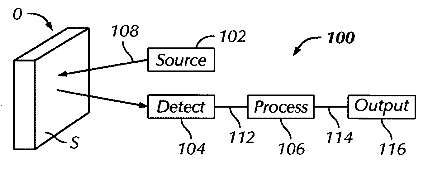
An example of a scattered light scanning system 100 is shown in FIG. 8. The energy source 102 includes a laser, such as a NEX model GLG5261 10 mW helium-neon laser. The beam 108 is directed through a series of stationary mirrors (not shown) and onto a scanner 140, such as a Newport model 425 rotating octagonal mirror. The mirror 140 rotates at a rate that produces 1,250 sweeps of the laser beam 108 per second over the specimen O. The beam 108 is directed by mirrors (not shown) to sweep vertically, while the octagonal mirror 140 rotates in a horizontal plane. A linear trace of 75 mm at the focal distance of a lens 142 of approximately 300 mm is covered by the scanning beam 108′. The surface area of the specimen O to be monitored is centered in the middle of the beam sweep, as close to the focal distance as possible. The beam spot width on the specimen surface S is approximately 60 μm.

The beam 108′ is reflected specularly from smooth areas of the surface S and scattered from rough ...

example 2

FIG. 9 shows an embodiment for monitoring surface condition of an aircraft component 150 in situ. As shown in FIG. 10, the source 102 and the detector section 104 are implemented into a sensor 152 that includes a detector 154 and a small diode laser (or LED) 156. The detector 154 is a small rugged detector attached directly to the component 150 under inspection. The laser 156 emits a beam 108 that is focused and scanned over a region of interrogation of the component 150. The scattered light 110 is then collected by an optical element (not shown), fed into the detector 154, and analyzed by an embedded processor 158 with on-board memory. The characteristics of the scattered light 110 include several types of information that can be used to assess the condition of the surface S of the component 150.

One change occurs when the spot of the scanned beam 108 crosses a microcrack. The light diffracted from a micro-crack is typically concentrated along a line that is normal to the crack di...

example 3

FIG. 11 illustrates an example of a system 100 for monitoring scattered light. Either the specular component or diffuse component of light, or both, can be detected. The energy source 102 includes a laser 162, a lens 164, and a scanner 166, and the detector section 104 includes a plurality of detectors 168a, 168b, . . . . Any number of detectors 168 may be positioned to enhance the reception of specular components of the reflected light 110, as represented by detector 168a, and any number of detectors 168 may be positioned to enhance the reception of diffuse components of the reflected light 110, as represented by detector 168b.

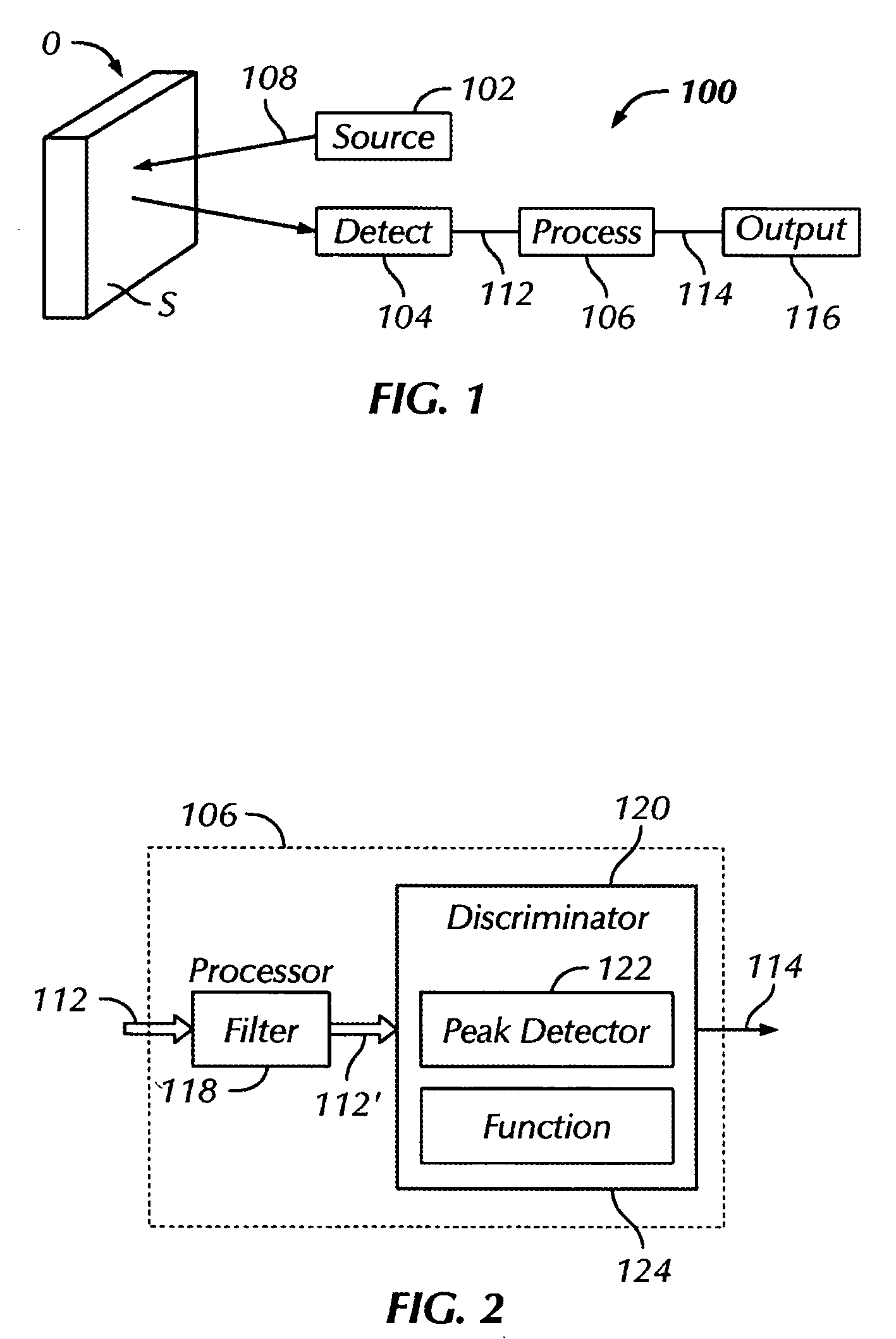
As the laser 162 is scanned over the surface, changes in light levels are produced by roughness of the surface S. Cracks on the order of the spot size (as mentioned above) produce a significant change in the detected signal 110; however, even sub-micron features can be detected. Using threshold circuitry 106, the scanned signal can be converted into a param...


PUM


Abstract

A system for quantifying surface characteristics detects and quantifies characteristics of a surface of an object. For example, the system may quantify changes in surface roughness without contacting the specimen and without requiring precise temporal or spatial stability. The system may also quantify the evolution or progression of a particular characteristic of a surface, such as a defect, a slipband, a crack, a microcrack, a pit, a damage feature, corrosion, a contour change, an impact crater, a change in residual stress, and so on. The system may include an energy source, a detector section, and a process section. The energy source transmits a source signal to the surface of the object. The source signal is specularly reflected and/or scattered by the surface to yield one or more received signals. The detector section receives the received signal and, in turn, provides a detector signal indicative of the received signal. The processor applies an algorithm to the detector signal to quantify an evolution in one or more characteristics of the surface.

Description

BACKGROUND OF THE INVENTION 1. Field of the Invention The present invention relates to techniques and methods for detecting and quantifying surface characteristics and material conditions using light scattering. 2. Description of the Related Art Detecting and monitoring fatigue damage is needed for preemptive failure repair or replacement of critical components in engineering systems. A macroscopic crack does not generally manifest until very late in the life of the component high cycle fatigue (HCF) conditions. However, surface structural changes and micro-cracks can occur much earlier on the surface and could possibly be used as a precursor for fatigue crack formation that leads to catastrophic failure. Therefore, it is of great importance to develop methods to quickly detect localized deformation and micro-cracking early in the fatigue life, well in advance of micro-crack coalescence and macroscopic crack growth. Early in the fatigue process, dislocations in crystalline soli...

Claims


Application Information

Patent Timeline
IPC IPC(8): G01N21/47G01N21/55G01N21/88
CPCG01N21/4738G01N21/88G01N21/55
Inventor EARTHMAN, JAMES C.MARKOV, VLADIMIR B.TROLINGER, JAMES D.DUNN-RANKIN, DEREKBUCKNER, BENJAMIN D.
Owner METROLASER
Why Eureka
Try Eureka