Mask for deposition, film formation method using the same and film formation equipment using the same

a technology of mask and film, applied in the direction of electroluminescent light sources, vacuum evaporation coatings, coatings, etc., can solve the problems of low reducing the dimensional accuracy of deposition layers on the substrate, and adverse effects on the quality of deposited layers, so as to achieve high dimensional accuracy and improve the utilization efficiency of deposition materials

Inactive Publication Date: 2005-02-17
TOYOTA IND CORP
View PDF3 Cites 113 Cited by
  • Summary
  • Abstract
  • Description
  • Claims
  • Application Information

AI Technical Summary

Benefits of technology

[0019] The present invention is directed to a mask for deposition, a film formation method using the mask and a film formation equipment using the mask, wherein deposition of a deposition material on the mask is suppressed

Problems solved by technology

However, the above-described conventional mask includes the following problems.
When deposition is repeated, the thickness of the deposition material deposited on the mask cannot be ignored compared to the thickness of the mask, resulting in adverse effect on quality of deposited layers.
Moreover, the mask receives heat from the deposition material and radiated heat from the deposition source, and undergoes thermal expansion, potentially decreasing th

Method used


Image

  • Mask for deposition, film formation method using the same and film formation equipment using the same
  • Mask for deposition, film formation method using the same and film formation equipment using the same
  • Mask for deposition, film formation method using the same and film formation equipment using the same

Examples


first embodiment

[0036] the invention will be explained below with reference to FIGS. 1 to 4.

[0037] The first embodiment is implemented by applying the invention to deposition of organic layers in an organic EL element.

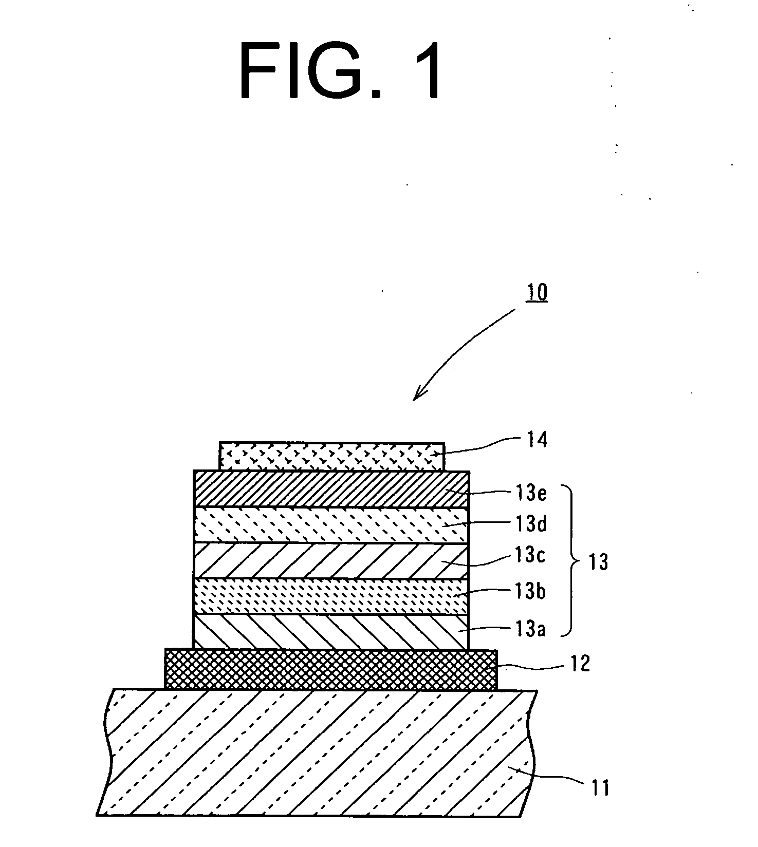
[0038] First, the organic EL element is explained. As shown in FIG. 1, an organic EL element 10 essentially includes a glass substrate 11, an anode 12, an organic layer 13, and a cathode 14.

[0039] The glass substrate 11 allows visible light to transmit therethrough and has the anode 12 as a transparent conductive layer formed on one surface of the glass substrate 11. The anode 12 is made of ITO (Indium Tin Oxide) or the like and is formed, for example, by sputtering.

[0040] Then, in the embodiment, as shown in FIG. 1, laminated on the anode 12 are a hole injection layer 13a, a hole transport layer 13b, a luminous layer 13c, an electron transport layer 13d, and an electron injection layer 13e in this order. In the embodiment, a combination of those functional layers is referred to as...

second embodiment

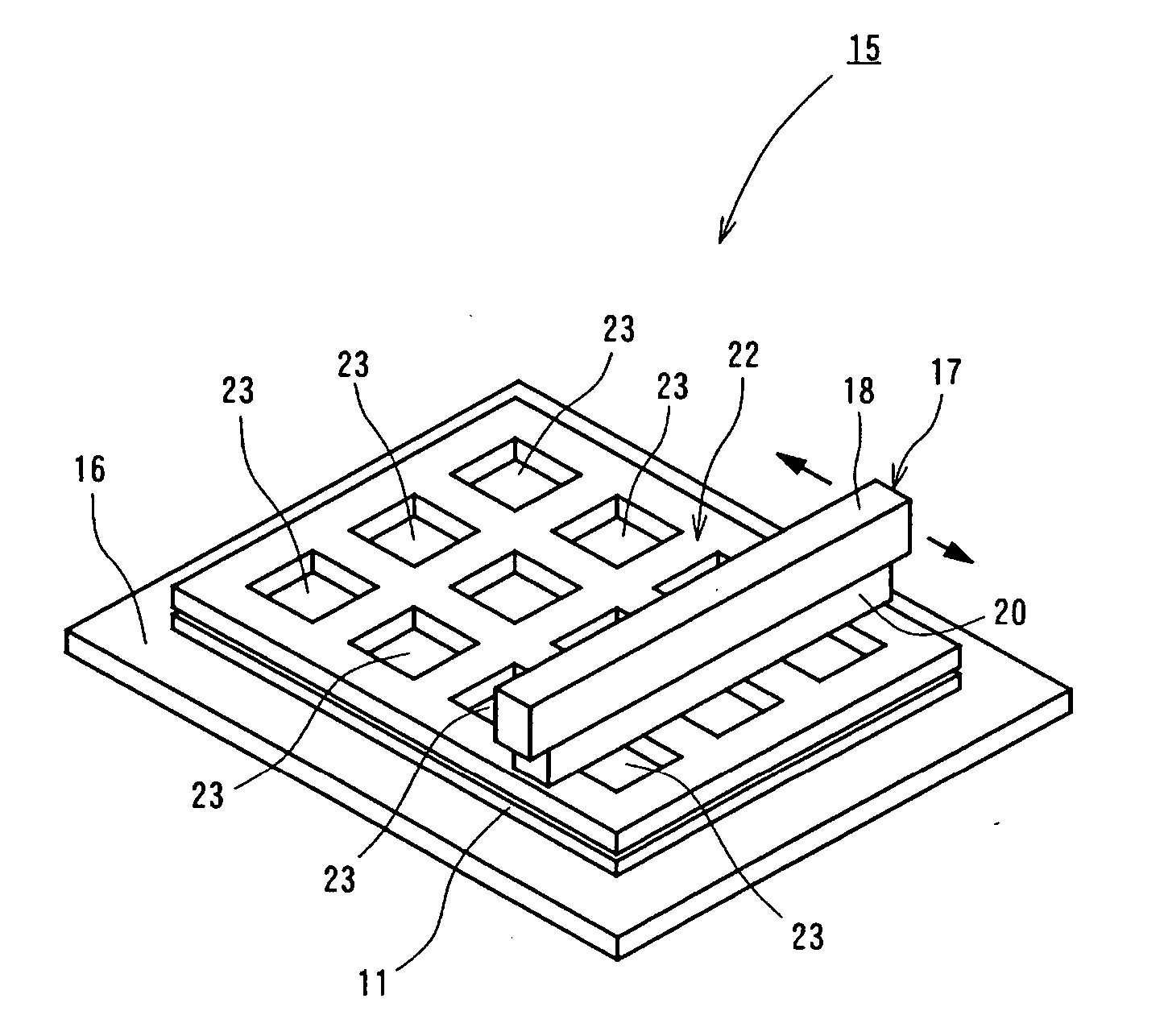
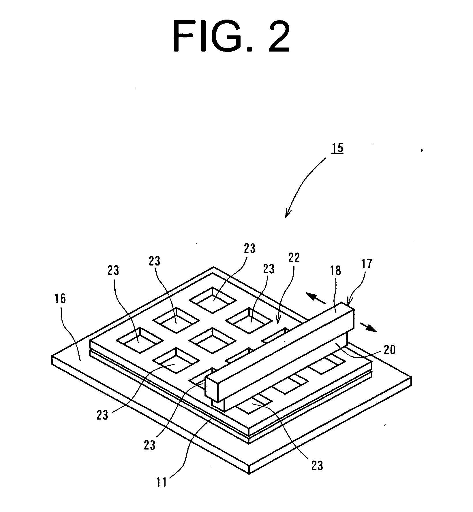
[0097] Now, a mask 30, will be explained with reference to FIG. 6.

[0098] In this embodiment, openings 31 of the mask 30 are different from those in the first embodiment.

[0099] In this embodiment, for explanatory convenience, some of the numerals used in the first embodiment are commonly used, and explanation of the configuration common or analogous to the first embodiment is omitted.

[0100] As shown in FIG. 6, the mask 30 includes, from the bottom up, a mask body 22a, the cooling member 22b, the heat insulation member 22c and the heating member 22d, and openings 31b, 31c, 31d of the cooling member 22b, the heat insulation member 22c and the heating member 22d all correspond substantially to an openings 31a of the mask body 22a.

[0101] The expression that the openings 31b to 31d correspond substantially to the opening 31a in the embodiment means that the opening 31a and the openings 31b to 31d are similar to or substantially similar to each other and further dimensions of the openi...

third embodiment

[0120] A mask 40 will now be explained with reference to FIG. 9.

[0121] The mask 40 according to the embodiment includes a mask body 40a, a cooling member 40b provided on the mask body 40a, and a heating member 40c provided on the cooling member 40b.

[0122] Similarly to the aforementioned embodiment, in this embodiment, openings 41b, 41c corresponding substantially to an opening 41a of the mask body 40a, are provided respectively in the heating member 40c and the cooling member 40b, and further, also prevent influence of a shadow due to the thickness portion of the mask 40. The openings 41b, 41c, in combination with each other, form a common inclined surface and form an opening 41 of the mask 40.

[0123] In the mask 40 according to this embodiment, the cooling member 40b is configured to include a thermoelectric element having cooling function upon passage of current.

[0124] In more detail, this embodiment employs a Peltier element constituted of a P type thermoelectric semiconductor...


PUM

PropertyMeasurementUnit
Lengthaaaaaaaaaa
Heataaaaaaaaaa

Abstract

A mask is interposed between a deposition source and a substrate for deposition. The mask has an opening for permitting a deposition material emitted from the deposition source to pass therethrough and forming a deposition layer of a desired pattern on the substrate. The mask includes a mask body and a heating member. The mask body has the opening. The heating member is heated during deposition and is arranged on a side of the mask body facing the deposition source. The heating member has an opening which corresponds substantially to the opening of the mask body.

Description

BACKGROUND OF THE INVENTION [0001] The present invention relates to a mask for deposition, a film formation method using the mask and a film formation equipment using the mask. [0002] An organic electroluminescent (EL) element including a pair of electrodes that consists of an anode and a cathode and are provided on a substrate, and an organic layer containing a light-emitting organic material and formed between the pair of electrodes has been known as an element capable of emitting light from the organic layer by passing current between the electrodes. The organic layer of the organic EL element typically includes a plurality of functional layers (a hole injection layer, a hole transport layer, a luminous layer, an electron transport layer, an electron injection layer, a buffer layer, a carrier blocking layer, etc.) and achieves a desired performance through combination, arrangement, etc. of those functional layers. [0003] For an organic EL element of a low molecular material among...

Claims


Application Information

Patent Timeline
IPC IPC(8): C23C14/04H05B33/10C23C14/12C23C14/24H01L51/40H01L51/50H01L51/56
CPCC23C14/042C23C14/12H01L51/56H01L51/0004C23C14/24H10K71/13H10K71/00H05B33/10
Inventor YAMAMOTO, KATSUYA
Owner TOYOTA IND CORP
Why Eureka
Try Eureka