
Cooling cannula system and method for use in cardiac surgery

a technology of cooling cannula and cardiac surgery, which is applied in the field of medical devices, can solve the problems of limited use, increased risk of angina and ischemia, and increased risk of complication of coronary artery bypass grafting (cabg)

Inactive Publication Date: 2005-02-17
EDWARDS LIFESCIENCES CORP
View PDF3 Cites 18 Cited by
  • Summary
  • Abstract
  • Description
  • Claims
  • Application Information

AI Technical Summary

Benefits of technology

[0026] One aspect of the present invention is to provide novel enhanced means for cooling select aspects of a patient's vasculature whereby cell, tissue and organ insult is mitigated or prevented.
[0027] Another aspect of the present invention provides novel enhanced means for cooling select aspects of a patient's cardiac anatomy whereby cell, tissue and general cardiac insult is mitigated or prevented.
[0028] Yet another aspect of the present invention provides tubular means for cooling select aspects of a patient's cardiac anatomy whereby cell, tissue and general cardiac insult is mitigated, extenuated or prevented.

Problems solved by technology

The risks and discomfort associated with angina and ischemia can be produced by the impaired blood flow resulting from CAD.
When pharmacological intervention or endovascular treatment do not fully address the issues, coronary artery bypass grafting (CABG) procedures may become necessary.
The internal mammary arteries can also used to provide a new blood supply beyond the point of arterial obstruction; however, since there are only two internal mammary arteries, their use is limited.
But the direct insertion of catheters into the right atrium can result in direct surgical trauma from the holes cut into these structures for catheter entry.
Such trauma can lead to bleeding, cardiac arrhythmias, air embolism and surgical adhesions.
The Huybregts cooling means, however, were limited to aspects of an inflatable balloon adapted to lie against the inside wall of the right atrium and along the transitions of the vena cava in the right atrium.
Likewise clinically in surgical practice, several limitations were found in the use of such balloons as the only cooling method.
First, the balloon was found to interfere with the manipulation of the heart required for surgery on the backside coronaries.
Using cannulae of the prior art, it has been found that there is a possible risk of damaging structures within the heart during this “flipping” maneuver.
This procedure creates difficulty with access to posterior grafts.
Prior art devices were also found to be deficient in producing a leak-free isolation of the right atrium.
Further, prior art devices were found to be deficient in contacting and therefore cooling the sino-atrial node.
Still further, prior art devices have been found to produce a possible risk of blockage of the coronary sinus.
Even further, prior art devices have been found to produce a possible risk of infringing and hence damaging the tricuspid valve.
Such an expanded conformation combined with deficient leak-free isolation of the right atrium can result in distention of the atrium during surgery, producing undesirable damage to anatomical structures.
In addition, backflow at the coronary anastomoses is expected, which compromises surgical visualization.
It is important to note that such incisions may damage electrical conductivity pathways and may result in reentry phenomenon ultimately manifesting itself in transient conduction abnormalities like arrhythmias and atrial fibrillation.
This approach is also time-consuming and laborious.
As a result, it is used for repairing or replacing cardia valves and is not usually used for CABG procedures.
It remains the case that prior devices, products, and methods currently available to medical practitioners have not adequately addressed the need for minimizing deficiencies in cardiac cooling and the potential for damage to cardiac anatomical structures.

Method used


Image

  • Cooling cannula system and method for use in cardiac surgery
  • Cooling cannula system and method for use in cardiac surgery
  • Cooling cannula system and method for use in cardiac surgery

Examples


Embodiment Construction

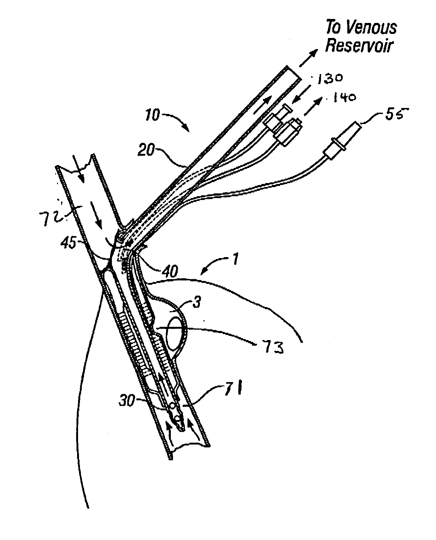
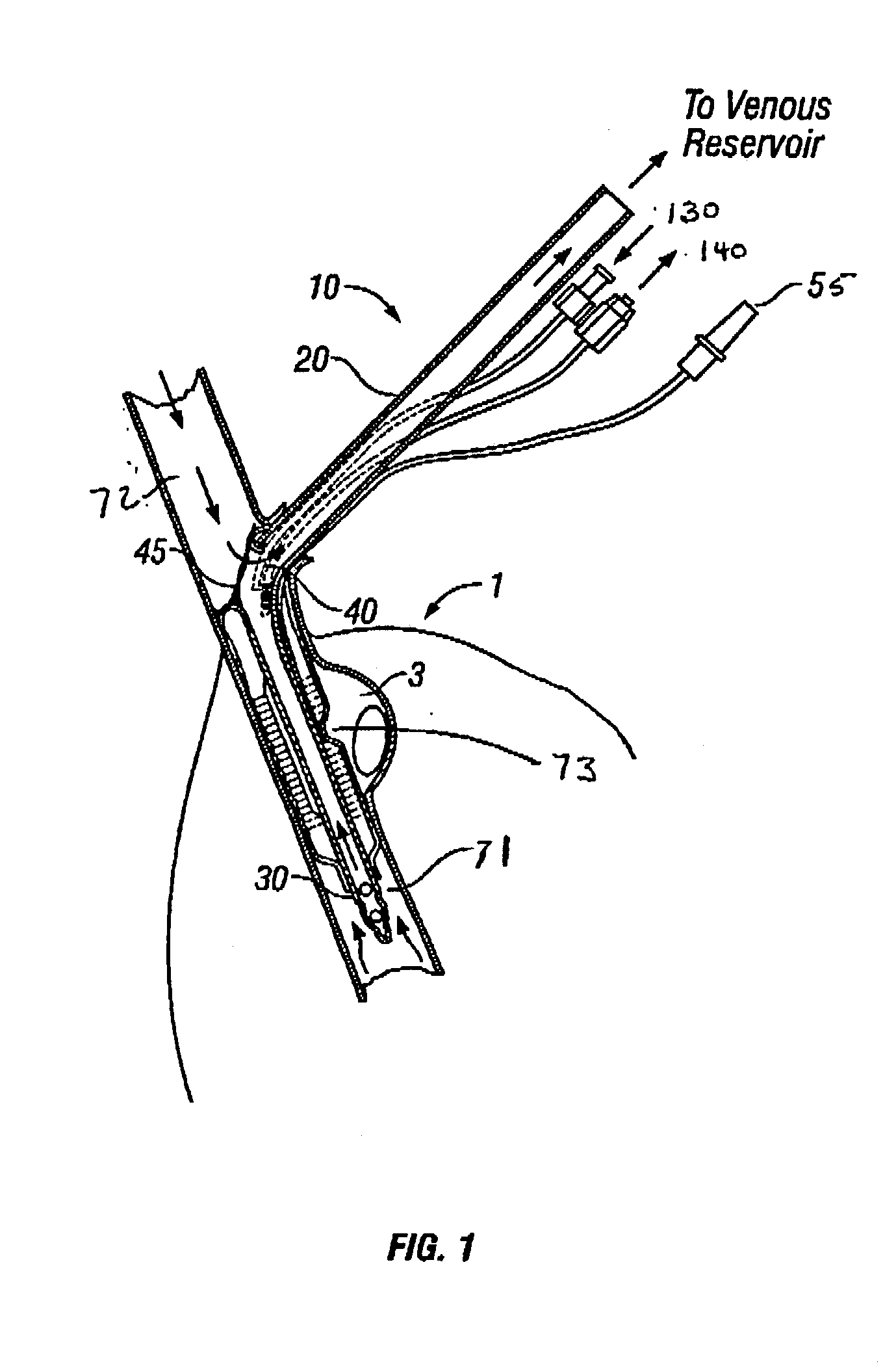
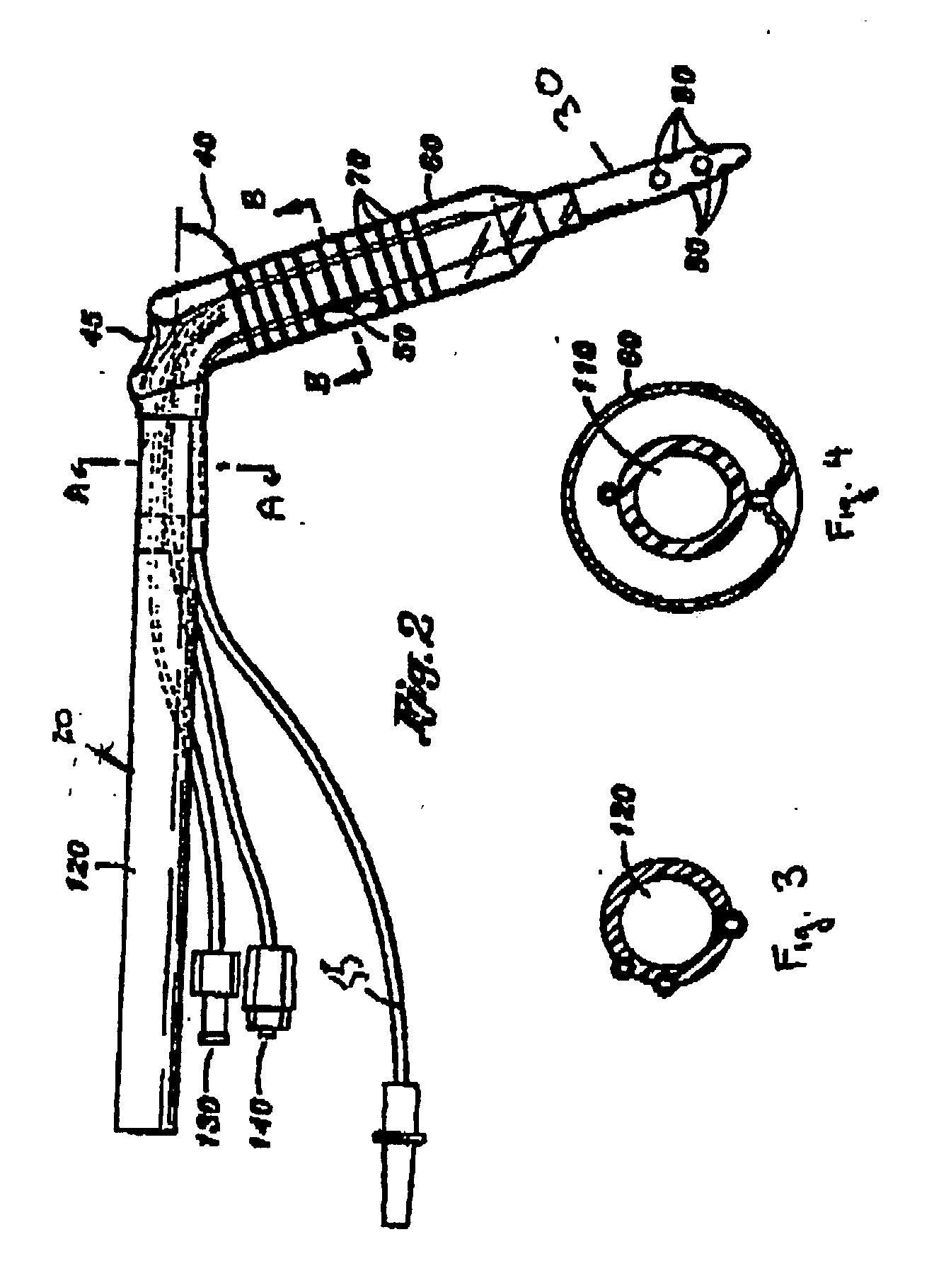
[0056] The present invention is directed to improved cooling cannula systems and methods for their use in cardiac surgery. The present invention may exist in numerous embodiments, including those that may be inserted peripherally thus avoiding the need for a major chest incision such a thoracotomy or median stemotomy.

[0057] By utilizing fluoroscopic or ultrasound imaging, the cooling device when designed in combination with a cannula may be precisely positioned such that upon inflation of inflatable members such as balloons, the flow of blood into the right atrium is fully blocked thereby achieving total heart bypass. The combined cooling device and cannula may use conventional heat transfer media cooled by refrigeration systems known in the art, or it may use thermoelectric cooling devices to accomplish the desired cooling.

[0058] By way of background, and in no way limiting the instant teachings, thermoelectric coolers are solid-state heat pumps that operate on the Peltier effect...


PUM


Abstract

A novel improved enhanced cardiac surgical method yields unexpected results by having an enhanced intraluminally emplaced cooling system. In preferred device embodiments improvements include a first means for draining venous blood from at least one of the right atrium, superior vena cava and inferior vena cava and an improved means for cooling involved luminal surfaces. Tissue insult and injury is substantially mitigated by engagement of the cooling means with select aspects of involved atrial tissue to augment transfer of heat. In one embodiment of the invention, the right atrium is cooled while the patient's body is maintained at a normothermic temperature during surgery. The alternate cooling mechanisms disclosed have applicability both on- and off-pump in a variety of procedures ranging from traditional open cardiac surgical repair and by-pass to endovascular procedures using percutaneous access and minimally invasive therapies.

Description

RELATED APPLICATIONS [0001] This application is a continuation-in-part of U.S. patent application Ser. No. 10 / 151,354, entitled “Cooling Cannula System and Method for Use in Cardiac Surgery,” filed May 20, 2002, which is incorporated herein in its entirety.FIELD OF THE INVENTION [0002] This invention pertains generally to medical devices and their methods of use for treatment of cardiovascular disease, and more particularly to specialized cannulae useful for implantation and / or emplacement within cavities or blood vessels of the body. The cannula of the present invention is particularly suited to mitigate, extenuate or otherwise positively impact cellular or tissue based insult during any cardio thoracic, cardiovascular, or related procedure by facilitating heat transfer away from the body tissue. BACKGROUND OF THE INVENTION [0003] Current technology addresses needs within the context of the world's most prevalent set of disease states, namely those loosely grouped under the term ca...

Claims


Application Information

Patent Timeline
Patent Type & Authority Applications(United States)
IPC IPC(8): A61B17/00A61B18/00A61F7/00A61F7/12
CPCA61B2017/00243A61B2018/00023A61F2007/126A61F2007/0075A61F7/123
Inventor HUYBREGTS, M.A.J.M.TODD, ROBERT J.CURTIS, ALISON S.
Owner EDWARDS LIFESCIENCES CORP
Learn More