High temperature splash plate for temperature reduction by optical reflection and process for manufacturing

a technology of optical reflection and high temperature, applied in the direction of machines/engines, efficient propulsion technologies, lighting and heating apparatus, etc., can solve the problems of undesired radiation directed to the side, increase the life of the splash plate, and increase the operating temperature of the splash plate. , the effect of thermal degradation of the splash plate is not as rapid

US20050039459A1Inactive Publication Date: 2005-02-24GENERAL ELECTRIC CO
16 Cites 11 Cited by

Patent Information

Authority / Receiving Office
US · United States
Patent Type
Applications(United States)
Current Assignee / Owner
Publication Date
2005-02-24
Estimated Expiration
Not applicable · inactive patent

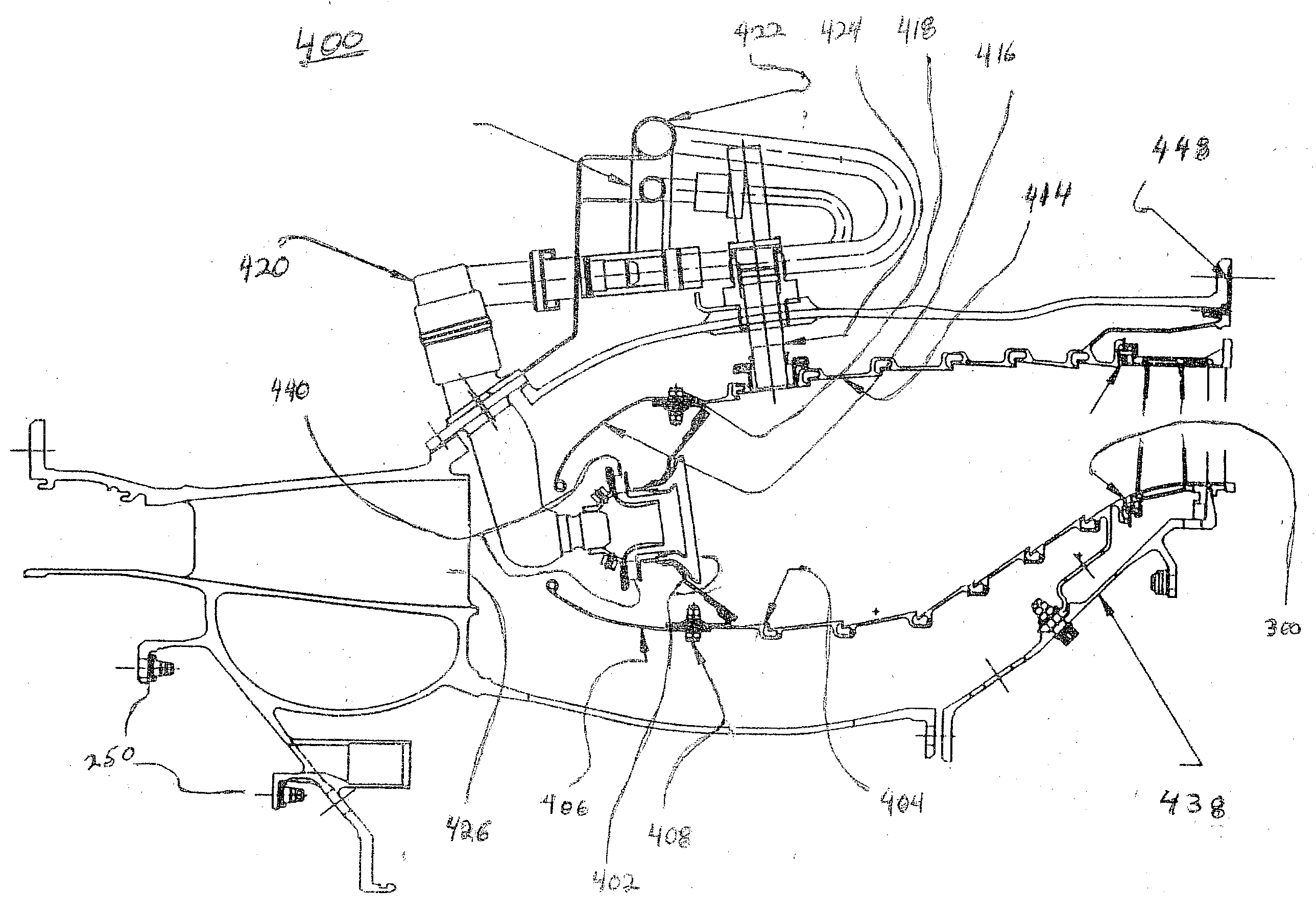
Smart Images

  • Figure 1
    Figure 1
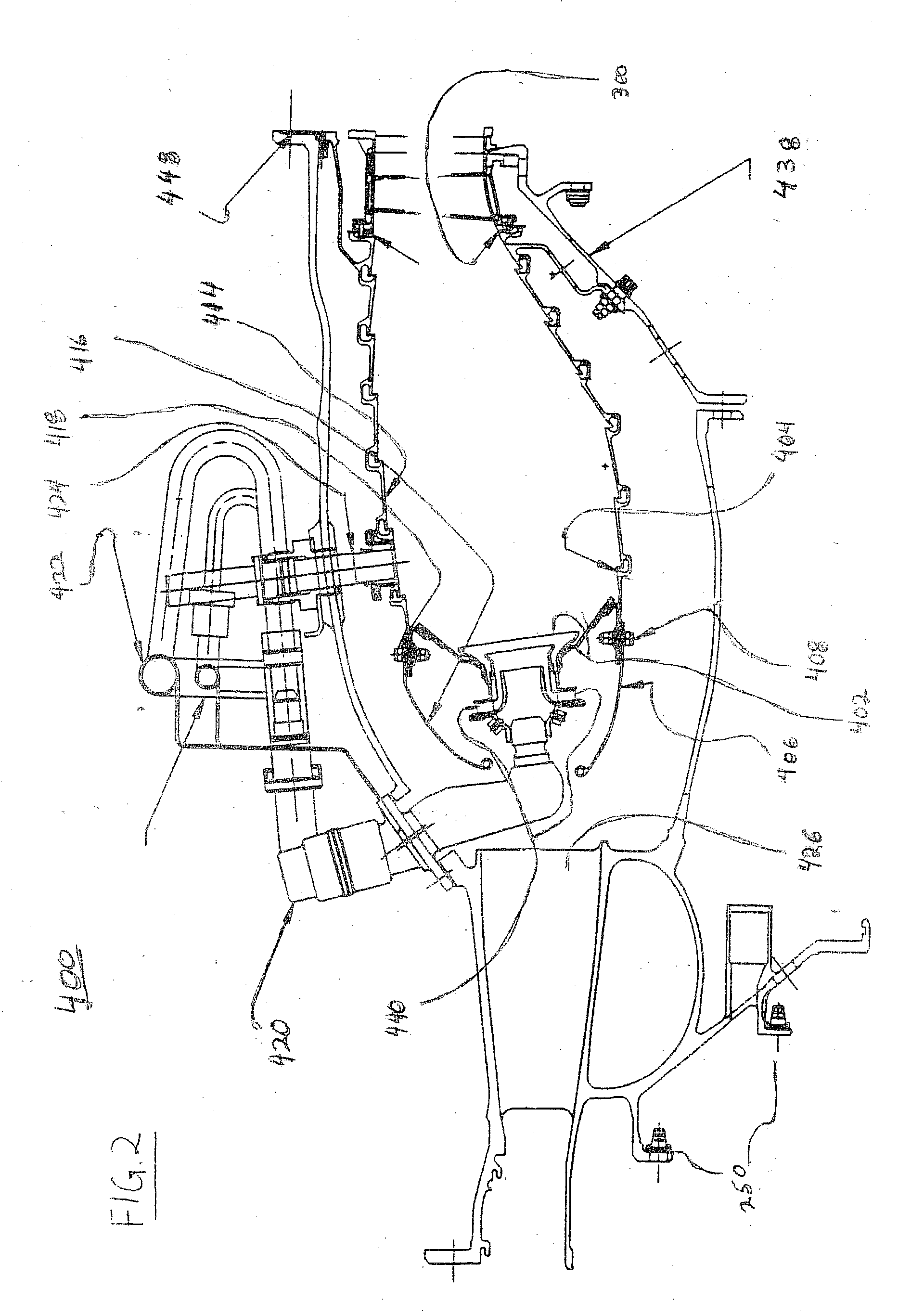
  • Figure 2
    Figure 2
  • Figure 3
    Figure 3
Patent Text Reader

Abstract

A high temperature splash plate for use in the combustor of a gas turbine engine that also is a specular optical reflector. A thin layer of a high temperature reflector is applied to the surface of the splash plate of the component that forms a boundary for hot combustion gases. The component typically includes a thermal barrier coating overlying the high temperature metallic component that permits the component to operate at elevated temperatures. The thermal barrier coating must be polished in order to provide a surface that can suitably reflect the radiation into the gas flow path. A thin layer of the high temperature reflector then is applied over the polished thermal barrier coating by a process that can adequately adhere the reflector to the polished surface without increasing the roughness of the surface. The surface reflects radiation in the direction of the turbine back into the hot gas flow path. The reflected radiation is not focused onto any other hardware component. The design of the splash plate is such that the radiation is not directed to an adjacent component, which only serves to increase the temperature of the wall of the component.
Need to check novelty before this filing date? Find Prior Art

Description

CROSS-REFERENCE TO RELATED APPLICATIONS

[0001] This Application is related to application Ser. No. ______, Attorney Docket No. 13DV-13957, filed contemporaneously with this Application on Dec. 31, 2002, entitled “IMPROVED HIGH TEMPERATURE CENTERBODY FOR TEMPERATURE REDUCTION BY OPTICAL REFLECTION AND PROCESS FOR MANUFACTURING” assigned to the assignee of the present invention and which is incorporated herein by reference, to application Ser. No. ______, Attorney Docket No. 13DV-13958 filed contemporaneously with this Application on Dec. 31, 2002, entitled “IMPROVED HIGH TEMPERATURE TURBINE NOZZLE FOR TEMPERATURE REDUCTION BY OPTICAL REFLECTION AND PROCESS FOR MANUFACTURING” assigned to the assignee of the present invention and which is incorporated herein by reference, and to application Ser. No. ______, Attorney Docket No. 13DV-13959 filed contemporaneously with this Application on Dec. 31, 2002, entitled “IMPROVED HIGH TEMPERATURE TURBINE NOZZLE FOR TEMPERATURE REDUCTION BY OPTICA...

Examples

Embodiment Construction

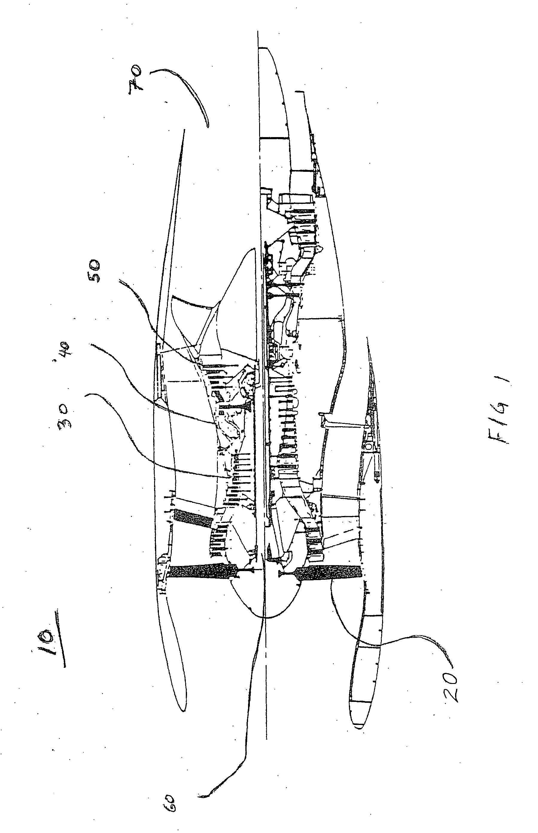
[0024]FIG. 1 is a cross section of a typical high bypass ratio turbofan engine 10. A simple description of the operation of such an engine follows. Air enters engine 10 through fan 20 and passes into compressor section 30, which includes a plurality of compressor stages. The compressed air is passed into the back portion of the engine. Some of the air is passed into the combustors 40, only one of which is illustrated, while some air is used for other purposes such as downstream cooling of components and cabin pressure. In the combustors 40, compressed air is mixed with fuel and ignited. The hot gases of combustion are moved downstream to the turbine section 50, which includes a plurality of turbine stages. Energy is extracted by the turbine section to drive the compressor stages 30 and fan 20 via the engine core 60. Hot gases moving beyond the turbine section 50 exit the exhaust portion 70 of engine 10, providing thrust which propels an aircraft forward.

[0025]FIG. 2 depicts a typic...