Electronic engine control with reduced sensor set

a sensor set and electronic engine technology, applied in the direction of electric control, machines/engines, instruments, etc., can solve the problems of accumulating vacuum in the intake tract, unable to time the engine by using a crankshaft trigger alone, etc., and achieve the effect of low cost and low complexity

Inactive Publication Date: 2005-02-24
ELECTROJET TECH INC
View PDF15 Cites 28 Cited by
  • Summary
  • Abstract
  • Description
  • Claims
  • Application Information

AI Technical Summary

Benefits of technology

[0026] A need therefore exists for a less complex fuel injection control system for cost sensitive applications. This invention presents a novel approach for a low cost, low complexity engine timing control, engine load determination, and air mass determination for fuel injection and ignition timing applications.
[0027] One aspect of the present invention is a method to reduce the complexity of the fuel injection system through using an intake air pressure sensor to determine engine position, phase, loading, and intake air mass. Pressure fluctuations are present on the intake stroke of the engine and are mechanically related to the opening and closing of the intake valve. The movement of the intake valve is mechanically linked to the crankshaft angle and hence the timing of the engine. There is an intake event every two crankshaft rotations in four-stroke applications, and once every crankshaft rotation for two-stroke engines. The presence of these pressure fluctuations is therefore indicative of engine phase (in four stroke applications), crankshaft position, engine speed, and can directly measure engine rpm. With this information, crankshaft position can be quantitatively measured and engine timing can be determined.
[0028] Through measuring the pressure of the incoming air charge one can implement a simple air mass measurement. Once the incoming air mass is calculated, the corresponding stoichiometric mass of fuel can be determined for injection into the combustion chamber at the appropriate time in the engine cycle via the engine controller and fuel injector.
[0029] Through monitoring the intake pressure signal, one can determine engine loading and use this as an input to the engine controller to determine fuel mass for injection. Engine load can also be used to modify the timing for spark ignition to prevent premature ignition or knock.
[0030] This invention can be used as a stand alone engine control mechanism using a single intake air pressure sensor, or in addition to a crankshaft trigger / position sensor, to accurately time an engine. This system offers less resolution than automotive “36-1” tooth crankshaft position sensors, yet offers excellent position sensing and engine timing at a much lower cost and complexity. Not only is crankshaft position detected, but also engine phasing, engine load, and air mass measurements can be determined with this technology. This technology allows an engine to be electronically controlled for the purpose of injecting fuel and timing the ignition events to help reduce engine emissions and gain efficiencies. The inherent non-invasive nature of this technology lends itself to be easily added to almost any pre-existing internal combustion engine configuration.
[0031] Thus, a manufacturer of engines would find it very easy to add the technology of fuel injection to their current product line. They would not need to hard tool or support multiple new sensors in their engine line. This invention allows for relative ease in the addition of fuel injection to engines not currently designed for the technology. The present invention allows for a low cost and extremely robust implementation of fuel injection and spark ignition control on an internal combustion engine.

Problems solved by technology

When an engine is throttle down from high engine speed to an idle speed, there is accumulated vacuum in the intake tract.
Using a crankshaft trigger alone does not allow an engine to be timed on a 720° cycle (in four stroke applications).

Method used


Image

  • Electronic engine control with reduced sensor set
  • Electronic engine control with reduced sensor set
  • Electronic engine control with reduced sensor set

Examples


Embodiment Construction

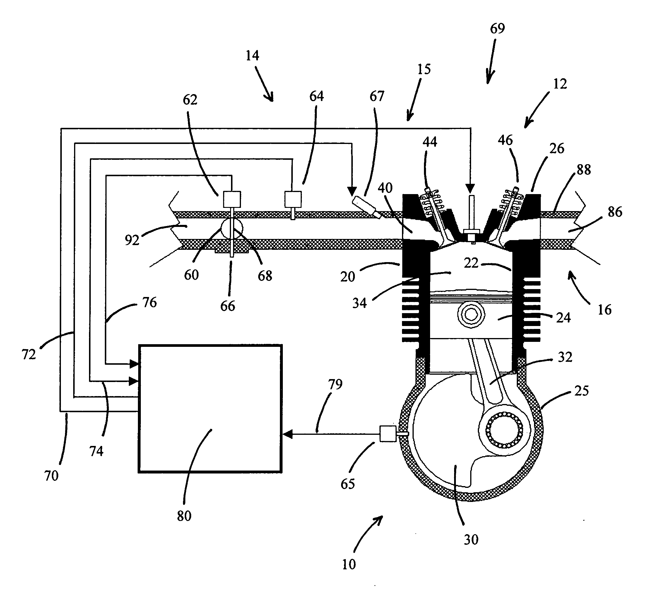
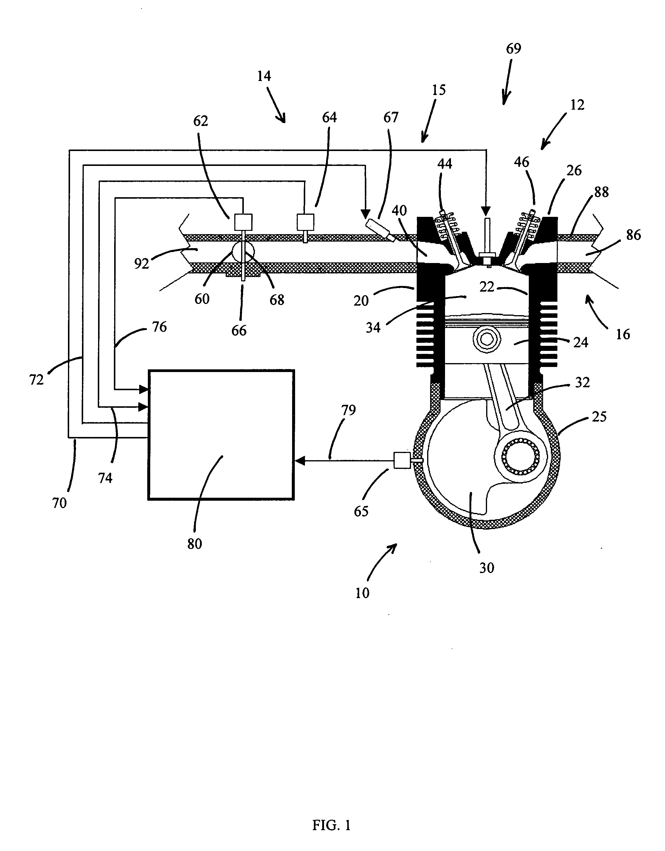
[0087]FIG. 1 shows an internal combustion engine 10 for use in an All Terrain Vehicle (ATV, or Four-wheeler). The present invention may also find utility in applications using internal combustion engines, such as, for example but without limitation, personal watercraft, small jet boats, off-road vehicles, heavy construction equipment, motorcycles, lawn tractors, and gas powered yard implements.

[0088] As used throughout this description, the terms “forward”, “front” and “fore” mean at or to the forward side of exhaust system 16, and the terms “rear”, “reverse” and “rearwardly” mean at or to the opposite side of the front side, unless indicated otherwise.

[0089] The engine 10 operates on a four-stroke combustion cycle. As shown in FIG. 1, the engine 10 includes a cylinder block 20, which defines a cylinder bore 22. In the illustrated embodiment, the engine 10 is of the single cylinder type.

[0090] It is to be noted that the engine may be of any type (V-type, Inline, W-type), may have...


PUM


Abstract

An engine control apparatus is disclosed for determining crankshaft position, engine phase, engine loading, and intake air mass of an internal combustion engine (10) through monitoring intake air pressure fluctuations (120). The opening of the intake valve (44) is mechanically linked to the crankshaft position of an engine. When the intake valve (44) opens it creates air pressure fluctuations in the air induction system (14) of the engine (10). The control apparatus is configured to determine intake air pressure fluctuations indicative of an intake air event (100 to 110) and thus a particular crankshaft position, and their corresponding period of the engine cycle. The controller then uses this information to determine crankshaft speed and position for the purpose of fuel injection and ignition timing of the internal combustion engine. Engine phase is also determined on four-stroke engines. Intake air pressure is used to determine intake air mass and loading of the engine. This combination results in a single sensor used in a system to determine intake air mass, engine loading, injected fuel mass, and to determine timing for fueling and ignition events. The engine may also include a crankshaft position sensor in combination with monitoring intake air pressure over time to increase resolution in the determination of crankshaft position.

Description

CROSS REFERENCE TO RELATED APPLICATIONS [0001] This application is a CIP of Ser. No. 10 / 642,530 filed Aug. 14, 2003 by the present inventor.FEDERALLY SPONSORED RESEARCH [0002] Not Applicable SEQUENCE LISTING [0003] Not Applicable BACKGROUND OF THE INVENTION—FIELD OF INVENTION [0004] The present invention is directed to an intake air pressure sensor assembly for an internal combustion engine, and in particular, a fuel-injected engine that communicates with a controller for determining intake air mass and controlling the fuel injectors and ignition timing of said engine. BACKGROUND OF THE INVENTION [0005] In all fields of engine design there is emphasis on fuel economy, engine performance, and most notably, engine-out emissions. Increased emissions restrictions have led to the necessity of a more accurate fuel metering process. Fuel injection systems have emerged as an accurate way to control the air and fuel mixture in an internal combustion engine and thus keep emissions low. The tr...

Claims


Application Information

Patent Timeline
Patent Type & Authority Applications(United States)
IPC IPC(8): F02D41/18F02D41/22F02D41/34
CPCF02D41/009F02D41/18F02D2200/0406F02D2041/227F02D41/222
Inventor SCHWULST, KYLE EARL EDWARD
Owner ELECTROJET TECH INC
Why Eureka
Try Eureka