Method of propulsion and attitude control in fluid environments and vehicles utilizing said method

a technology of fluid environment and propulsion method, applied in the direction of underwater equipment, special-purpose vessels, vessel construction, etc., can solve the problems of reducing efficiency, reducing the efficiency reducing the efficiency of the method of propulsion and attitude control, so as to achieve the effect of increasing the overall performan

Inactive Publication Date: 2005-02-24
RICHARD TYLER FRAZER
View PDF24 Cites 42 Cited by
  • Summary
  • Abstract
  • Description
  • Claims
  • Application Information

AI Technical Summary

Benefits of technology

[0023] Located at the extreme aft of the fuselage may be a vertical tail and rudder assembly to control turning movements that may also consist of a horizontal elevator or split elevators mounted to the top of the tail assembly to effect lift, pitch, roll and yaw.
[0024] An emphasis on simplicity, modularity and flexibility of construction, performance and role is inherent in the design of the invention. An added emphasis is on the scalability of said invention, with overall performance increasing with the scale of vehicles utilizing the invention.

Problems solved by technology

Submersibles, surface marine vehicles, surface-effect vehicles, fixed-wing aircraft, rotary wing aircraft and a wide assortment of theoretical and conceptual vehicles tend to use methods of propulsion and control that are not compatible with each other although there are hybrid type vehicles designed to function in more than one environment with less than optimum performance in these environments.
Because this method of propulsion and attitude control is less efficient than common screw-type propellers, mounted upon axes parallel with the longitudinal centerline of the vehicle, there is no known use of this method for marine submersibles.
Along with the reduction of efficiency, this method has other inherent disadvantages, including: the relatively small pump intake(s), which are located at the bottom of the vehicle so as to remain in the fluid stream upon which the pumps act upon, may become obstructed, debris may be ingested by the impeller, damaging the impeller, seals, bearings and / or other drive components and said method requires the impeller to be driven at a high rate of speed for optimum performance, which in turn reduces the lifespan of many drive components.
This method of propulsion is specifically designed to operate in a marine environment and may not be modified in any known way to transcend said environment without other means of propulsion and control.
Along with the assumed necessity of separate means for lift and longitudinal propulsion and attitude control, the disadvantages common to hovercraft design include the inability to operate safely and efficiently: in rough water conditions, high winds, on steep grades, and over large obstacles and rough terrain relative to the size of the vehicle.

Method used


Image

  • Method of propulsion and attitude control in fluid environments and vehicles utilizing said method
  • Method of propulsion and attitude control in fluid environments and vehicles utilizing said method
  • Method of propulsion and attitude control in fluid environments and vehicles utilizing said method

Examples


Embodiment Construction

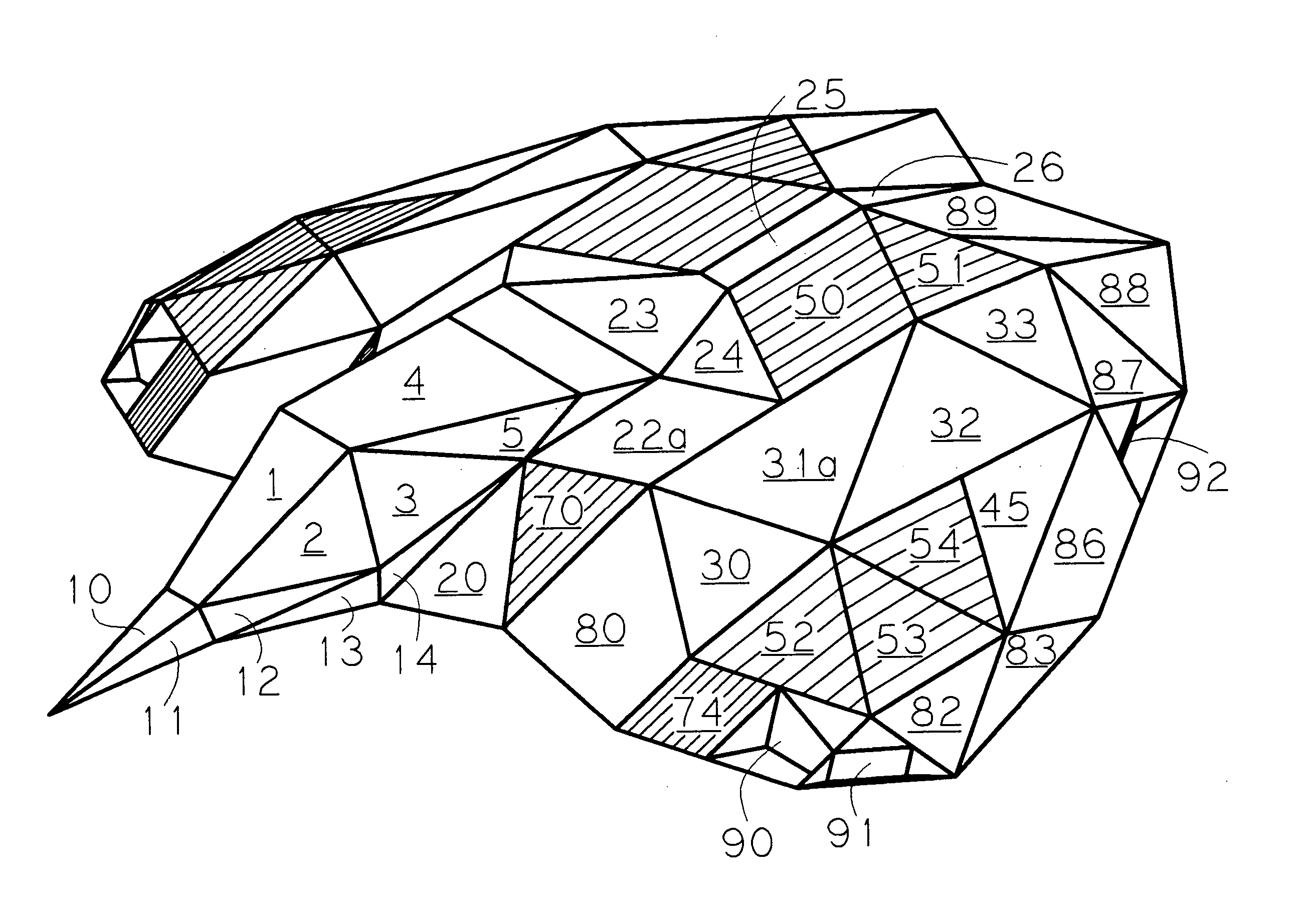
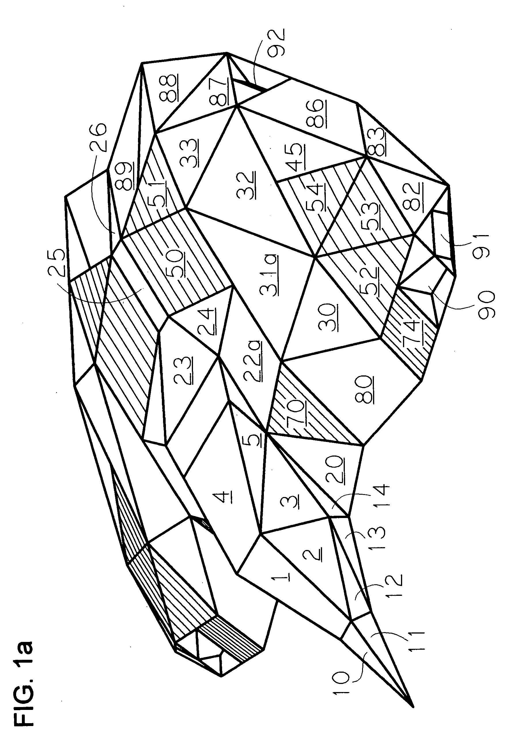
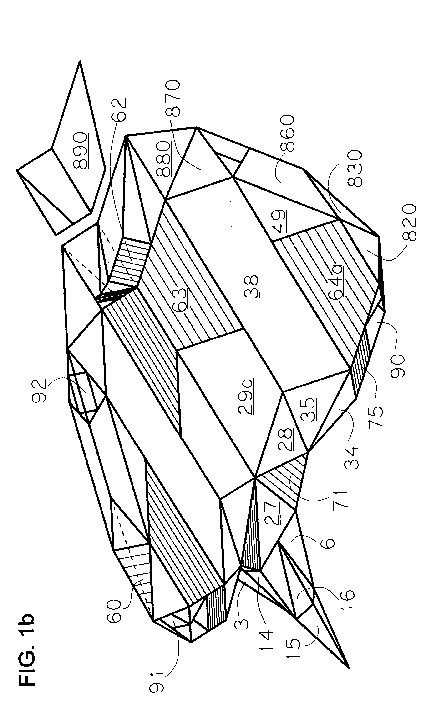
[0057] As many components, structures and surfaces are identical in construction and function, for left and right sides of the vehicle, to reduce repetition and aid clarity to the drawings, components, structures and surfaces of only one side of the craft are labeled. Left and right side components, structures and surfaces shall be designated in the description, when necessary, with a suffix “-l,” designating left, or “-r,” designating right. For example 31a-l, shall designate the wing assembly surface / structure, 31a, on the left-hand side of the craft. The exception to this rule concerns only components, structures and surface which are centrally located on the fuselage, this exception includes: 1,4,10, 21a, 21b, 23, 25, 26, 27, 100, 104, 105, 106 and 190.

[0058] As many components, structures, and surfaces of two-cell, three-cell and four-cell vehicles which utilize the invention are nearly identical in construction and function, to reduce repetition, said components, structures a...


PUM


Abstract

A method of propulsion and attitude control in fluid environments is disclosed by examples of preferred embodiments of vehicles utilizing said methodology. The preferred embodiment of a vehicle utilizing said invention comprises at least one pair of left and right wing assemblies of an airfoil profile separated by a fuselage that combine to form a fluid dynamic body. Each wing assembly houses within its interior at least two longitudinally adjacent, counter-rotating drive-fans mounted on fixed approximately vertical axes that are capable of being powered by various means. Each wing assembly has operable interior and exterior venting means that control fluid flow to, from and between respective drive-fans. Each wing assembly has control surfaces at its trailing edge and is itself hinged to the fuselage with means to change the dihedral of the wing assembly. Each wing assembly has surfaces of designed permeability that create a dynamic laminar flow envelope about the vehicle. The fuselage comprises a forward cockpit/cabin area and a fluid channel located laterally between left and right wing assemblies with means to control flow between said wing assemblies. The preferred embodiment may be constructed to any scale while using various construction techniques common knowledge to marine and aircraft construction, as well as easily modified to suit role and performance.

Description

CROSS REFERENCE TO RELATED APPLICATIONS [0001] Not applicable. STATEMENT REGARDING FEDERALLY SPONSORED RESEARCH OR DEVELOPMENT [0002] Not applicable. REFERENCE TO A MICROFICHE APPENDIX [0003] Not applicable. BACKGROUND OF THE INVENTION [0004] The current invention relates, in general, to methods of propulsion and attitude control applicable to: marine submersibles, marine surface vehicles, surface-effect vehicles, conventional aircraft, and V / STOL aircraft. More specifically, the invention relates to a method of propulsion and attitude control that utilizes longitudinally adjacent, counter-rotating, drive-fans mounted on fixed, approximately vertical axes within airfoil wing assemblies of controllable dihedral. [0005] The majority of designs and patents related to propulsion and attitude control in fluid environments are specialized to function in three distinct environments: marine, surface-effect and atmospheric flight. Submersibles, surface marine vehicles, surface-effect vehicle...

Claims


Application Information

Patent Timeline
Patent Type & Authority Applications(United States)
IPC IPC(8): B63B1/16B63G8/00B64C1/00B64C3/42B64C13/04B64C13/50B64C29/00
CPCB63B1/16B63G8/00B64C1/00B64C3/42B64C13/503B64C29/0025Y02T50/44B64C2001/0063B64C2001/0072B64C2001/0081Y02T50/12Y02T50/145Y02T50/433B64C2001/0045Y02T50/10Y02T50/40
Inventor FRAZER, RICHARD TYLER
Owner RICHARD TYLER FRAZER
Why Eureka
Try Eureka