
Portable laser

a laser and portability technology, applied in the direction of active medium materials, manufacturing tools, welding/soldering/cutting articles, etc., can solve the problems of large oxygen consumption rate (several ftsup>3/sup>/minute), clogging of the nozzle, and large/heavy oxygen gas cylinders, so as to increase the area of material modified and increase the kerf of the cut

Inactive Publication Date: 2005-02-24
NUFERN
View PDF19 Cites 54 Cited by
  • Summary
  • Abstract
  • Description
  • Claims
  • Application Information

AI Technical Summary

Problems solved by technology

When the requirement calls for cutting of relatively thick sections at high speeds (e.g., emergency uses), the choice is usually limited to some type of thermal energy based cutting system.
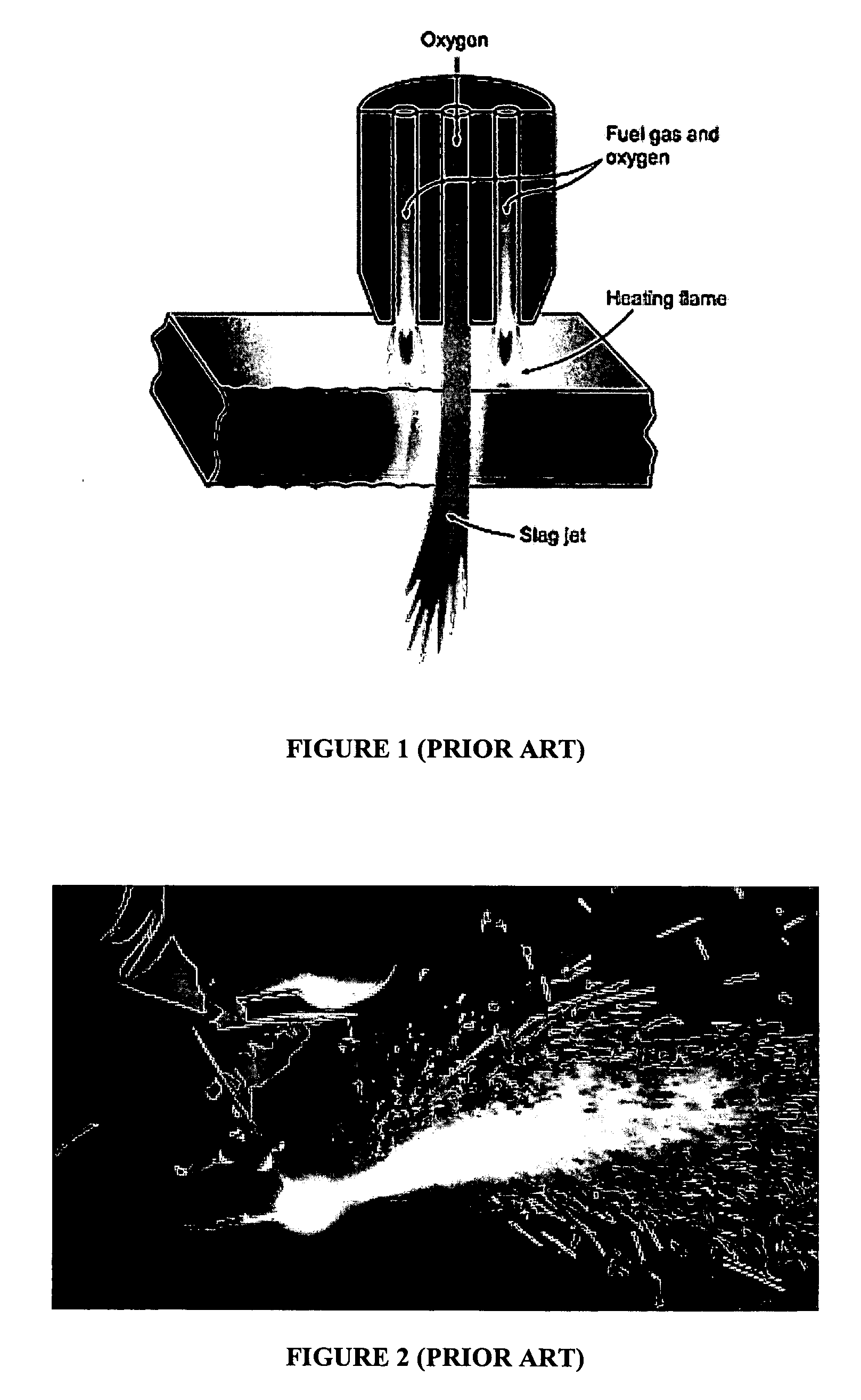
One disadvantage from the portability perspective is the large oxygen consumption rate (several ft3 / minute, depending on plate thickness and cutting speed) which can require large / heavy oxygen gas cylinders.
Also, the cutting nozzle is in close proximity to the cutting surface and this result in the clogging of the nozzle.
Disadvantages include air jet induced molten metal ejection over large distances, and excessive noise due to high electric current (up to 2 kA) and high air pressure (80-100 psi).
The extremely high power demands and oxygen pressure needs, do not lend this technique to adapt to a portable system (power requirements mandate large power packs, and high oxygen pressures mandate bulky cylinders).
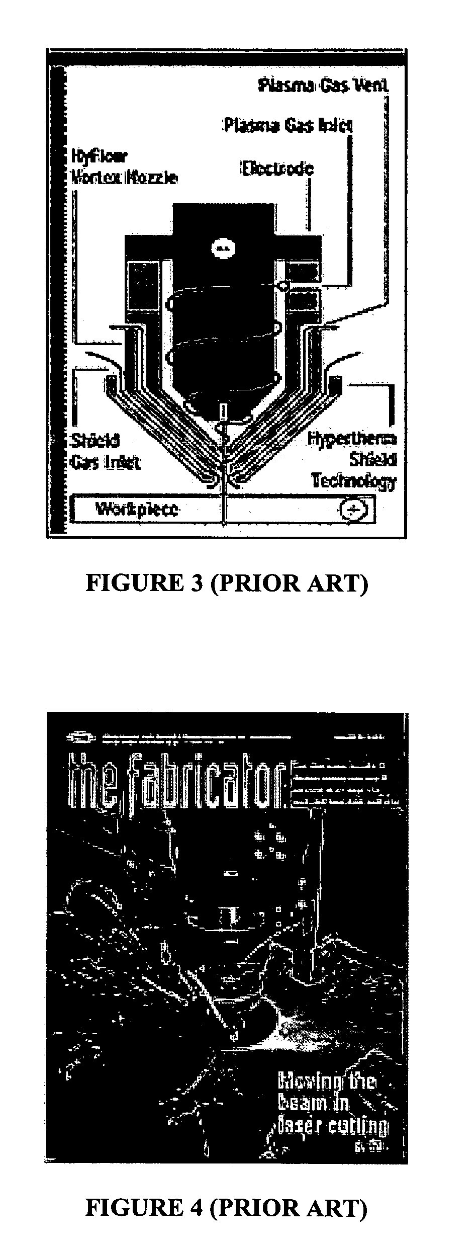
Major disadvantages include low electrical-to-thermal energy conversion efficiency (100 kW output needs over 200 kW input), inability to cut thicker gauge metals, and splash back that causes torch fouling.
Like air arc cutting, plasma cutting needs very high power which does not lend itself well to portability.

Method used


Image

  • Portable laser
  • Portable laser
  • Portable laser

Examples


Embodiment Construction

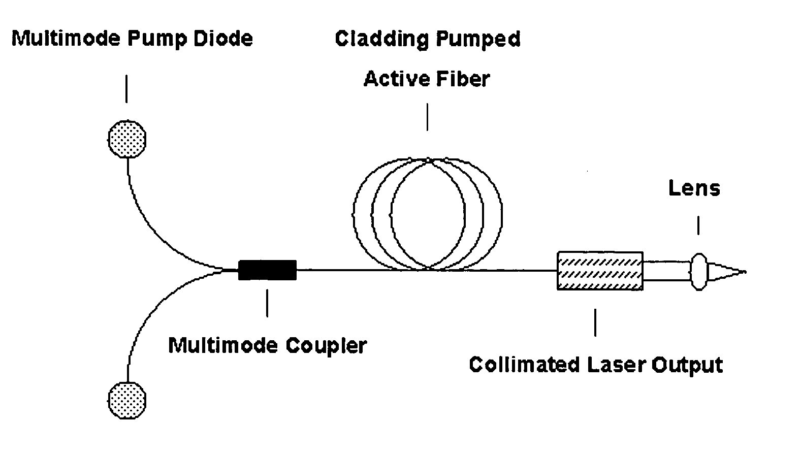
[0025] Among the many cutting techniques, the inventors consider laser cutting to be the most promising from the point of view of yielding an improved apparatus, such as a portable apparatus having a reduced weight or size. This assessment is based on relatively modest requirements of the input power supply unit and the gas consumption rate. Laser cutting can also afford the opportunity to provide the thermal energy directly to the site where it is needed. In other cutting systems thermal energy can be transferred to the cutting site via heavy reliance on conduction or convection or by both the mechanisms. Using suitable optics, the laser beam focal spot size can often be reduced to increase brightness (energy density), beam quality can often be improved (more power. accommodated in the fundamental mode), and working distance can often be increased. One or more of these factors can help contribute to higher cutting speed and decreased fouling of the laser delivery optics.

[0026] Cut...


PUM

PropertyMeasurementUnit
ignition” temperatureaaaaaaaaaa
pressureaaaaaaaaaa
poweraaaaaaaaaa

Abstract

Methods and apparatus for modifying a material with a laser light beam, such as, for example, a laser light beam provided by portable laser, such as, for example, a portable optical fiber laser.

Description

CROSS-REFERENCE TO RELATED APPLICATION [0001] This application claims priority to provisional patent application 60 / 478,680, filed Jun. 12, 2003 and entitled “Portable Laser”, and which is herein incorporated by reference.FIELD OF THE INVENTION [0002] The present invention relates to methods and apparatus for modifying, such as cutting, a material, and more particularly, to laser apparatus and methods for modifying a material. BACKGROUND OF THE INVENTION [0003] Modifying a material, such as a metal, can include machining, cutting, ablating, heat treating, such as hardening or annealing, as well as other operations. For purposes of illustration, and without limitation, we describe cutting techniques for metal in the most detail. Cutting refers to processes that can include removal of metal (or alloy), or other material, from the workpiece by the application of mechanical or thermal energy. When the requirement calls for cutting of relatively thick sections at high speeds (e.g., emerg...

Claims


Application Information

Patent Timeline
Patent Type & Authority Applications(United States)
IPC IPC(8): B23K26/00B23K26/03B23K26/06B23K26/14B23K26/38H01S3/067H01S3/0941H01S3/10H01S3/16H01S3/30
CPCB23K26/0096B23K26/4005B23K26/032B23K26/034B23K26/06B23K26/123B23K26/14B23K26/147B23K26/1476B23K26/381B23K2203/04H01S3/025H01S3/067H01S3/0941H01S3/1618B23K26/03B23K26/382B23K26/40B23K2103/04B23K2103/50
Inventor SEIFERT, MARTINALAM, MANSOOR
Owner NUFERN
Learn More