Time of flight mass spectrometer

Active Publication Date: 2005-03-03
SHIMADZU CORP +1
View PDF15 Cites 41 Cited by
  • Summary
  • Abstract
  • Description
  • Claims
  • Application Information

AI Technical Summary

Benefits of technology

[0005] An object of the present invention is therefore to improve the accuracy of TOF-MSs by el

Problems solved by technology

In many cases, however, it is difficult to incorporate a long straight path in a TOF-MS due to the limited overall size, so that various measures have been taken to effectively lengthen the flight length.
Since these error-causing factors are unrelated to mass to charge ratio of ions, the len

Method used


Image

  • Time of flight mass spectrometer
  • Time of flight mass spectrometer
  • Time of flight mass spectrometer

Examples


Embodiment Construction

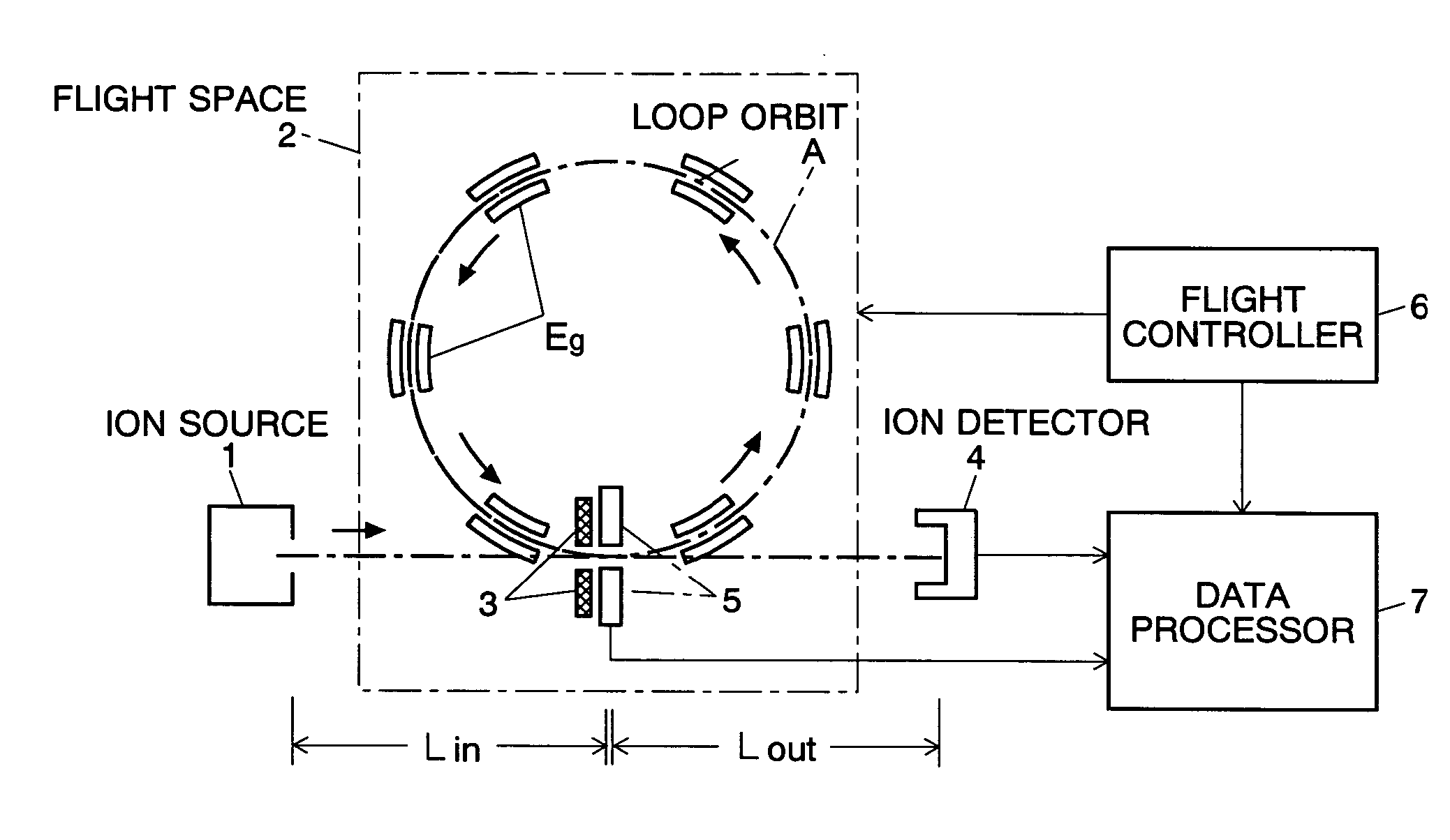
[0030] A TOF-MS embodying the present invention is described using FIG. 1. Though the TOF-MS of FIG. 1 has a circular orbit, the present invention is also applicable to an elliptic orbit, an “8” figured orbit as shown in FIG. 5, and any other loop orbit. The present invention is even applicable to TOF-MSs having a straight flight path on which ions reciprocate more than once between the entrance and exit electrodes 8 and 9 as shown in FIG. 6.

[0031] In the TOF-MS of FIG. 1, ions starting from the ion source 1 are introduced in the flight space 2, where they are guided by the gate electrodes 3 to the loop orbit A. Ions fly the loop orbit A once or more than once, leave it, exit the flight space 2, and arrive at and are detected by the first ion detector 4. On the loop orbit A is provided another ion detector (second ion detector) 5.

[0032] The first ion detector 4 uses a general ion detector of the destructive type, e.g., a photomultiplier, used in conventional TOF-MSs in which ions ...


PUM


Abstract

In a time of flight mass spectrometer (TOF-MS) of the present invention, a flight controller makes ions fly a loop orbit a predetermined number of turns, and an ion detector detects the ions at each turn of the flight. A flight time measurer measures the length of flight time of ions of a same mass to charge ratio at every turn, and a data processor constructs a spectrum of flight time. The data processor further computes the Fourier transformation of the spectrum, and determines the mass to charge ratio of the ions based on a frequency peak appearing in the Fourier transformation.

Description

[0001] The present invention relates to a time of flight mass spectrometer (TOF-MS), and especially to one in which ions repeatedly fly a loop orbit or a reciprocal path. BACKGROUND OF THE INVENTION [0002] In a TOF-MS, ions accelerated by an electric field are injected into a flight space where no electric field or magnetic field is present. The ions are separated by their mass to charge ratios according to the time of flight until they reach and are detected by a detector. Since the difference of the lengths of flight time of two ions having different mass to charge ratios is larger as the flight path is longer, it is preferable to design the flight path as long as possible in order to enhance the resolution of the mass to charge ratio of a TOF-MS. In many cases, however, it is difficult to incorporate a long straight path in a TOF-MS due to the limited overall size, so that various measures have been taken to effectively lengthen the flight length. [0003] In the Japanese Unexamine...

Claims


Application Information

Patent Timeline
IPC IPC(8): B01D59/44G01N27/64G01N27/62H01J49/00H01J49/40
CPCH01J49/408H01J49/027
Inventor YAMAGUCHI, SHINICHIISHIHARA, MORIOTOYODA, MICHISATOOKUMURA, DAISUKE
Owner SHIMADZU CORP
Why Eureka
Try Eureka