Method of writing to a multi-state magnetic random access memory cell

a multi-state, memory cell technology, applied in the direction of digital storage, instruments, semiconductor devices, etc., can solve the problems of poor write endurance of flash memory, high voltage requirements, slow program and erase times, etc., and achieve the effect of reducing the number of cycles of flash memory

Inactive Publication Date: 2005-03-03
EVERSPIN TECHNOLOGIES
View PDF7 Cites 45 Cited by
  • Summary
  • Abstract
  • Description
  • Claims
  • Application Information

AI Technical Summary

Problems solved by technology

Disadvantages of FLASH memory include high voltage requirements and slow program and erase times. Also, FLASH memory has a poor write endurance of 104-106 cycles before memory failure.
Hence, FLASH memory is limited in the dimensions to which it can be scaled.
As the lateral dimension of previously known MRAM devices decrease, three problems may occur.
First, the switching field increases for a given shape and film thickness, requiring a larger magnetic field to switch.
The energy barrier determines the data retention and error rate of the MRAM device and unintended reversals can occur due to thermo fluctuations (superparamagnetism) if the barrier is too small.
A major problem with having a small energy barrier is that it becomes extremely difficult to selectively switch one MRAM device in an array.
With photolithography scaling becoming more difficult at smaller dimensions, MRAM devices will have difficulty maintaining tight switching distributions.

Method used


Image

  • Method of writing to a multi-state magnetic random access memory cell
  • Method of writing to a multi-state magnetic random access memory cell
  • Method of writing to a multi-state magnetic random access memory cell

Examples


first embodiment

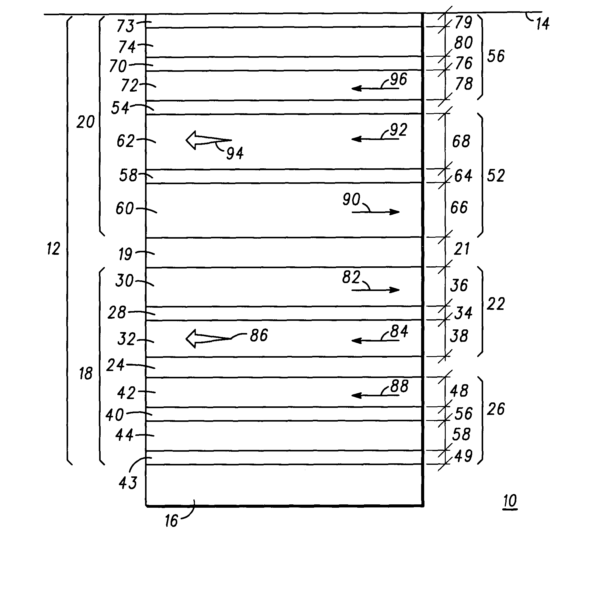
As previously mentioned, bit 20 functions similarly to bit 18; however in this first embodiment as described, the tunnel barriers 24 and 54 are deposited with different thicknesses, giving a different resistance range for each bit 18 and 20, such as 2K and 4K ohms with MR of 50%. For example, MR=□R / Rlow=(Rhigh−Rlow) / Rlow. For 2 bits, 4 separate resistance states may be determined as shown in the chart below.

BIT 2 (0)BIT 2 (1)BIT 1 (0)R1low + R2lowR1high + R2lowBIT 1 (1)R1low + R2highR1high + R2high

Magnetic regions 22 and 52 are thus designed to provide a higher switching field either through the magnetic layer thickness, material anisotropy, or antiferromagnetic exchange strength. Bit 18 has a lower toggle field and can be switched when the applied field is above its threshold. Bit 20 has a higher switching threshold. In the field range above the bit 18 threshold and below the bit 20 threshold, bit 18 can be toggled without disturbing bit 20. For fields above the bit 20 threshold, ...

second embodiment

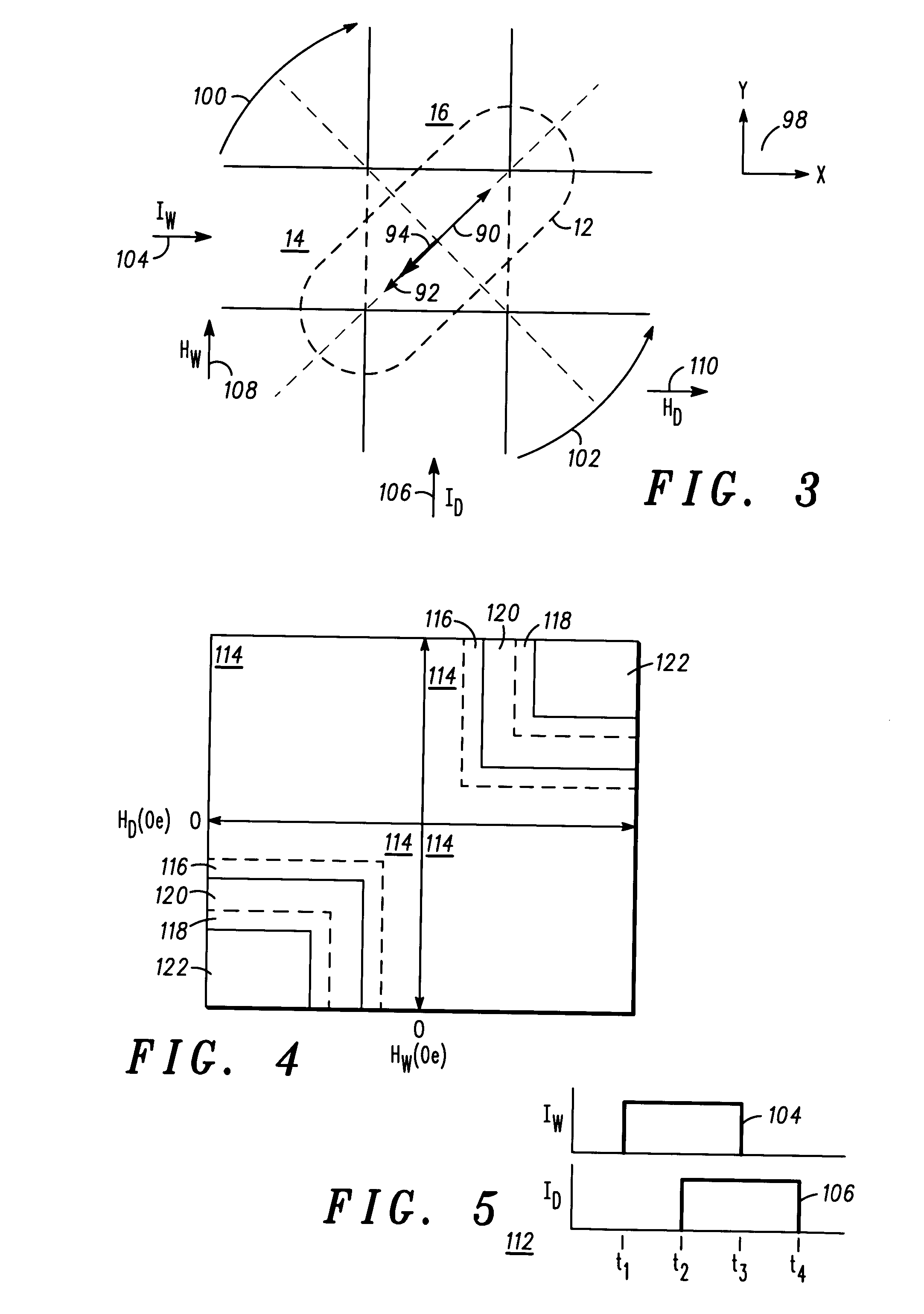
There are seven regions of operation illustrated in FIG. 7 for the second embodiment which includes both a direct and a toggle mode. In a region 114 there is no switching, e.g., there is not sufficient current in either the word line 14 or digit line 16 to create a strong enough magnetic field to “write” the bits 18 and 20. For MRAM operation in a regions 130 and 134, the direct writing method is in effect for writing bit 18 (region 130) and bit 20 (region 134),. When using the direct writing method, there is no need to determine the initial state of the MRAM device because the state is only switched if the state being written is different from the state that is stored. The selection of the written state is determined by the direction of current in both word line 14 and digit line 16. For example, if a ‘1’ is desired to be written, then the direction of current in all the lines will be positive. If a ‘1’ is already stored in the element and a ‘1’ is being written, then the final sta...

third embodiment

the invention allows for the programming of the bits 18 and 20 separately using the same magnitudes of the currents in the word line 14 and the digit line 16. This third embodiment uses a structure similar to that illustrated in FIG. 1, except bits 18 and 20 are patterned separately with an orthogonal orientation of their long axes as shown in FIG. 8. Bit 18 is oriented at +45 degrees and bit 20 is oriented at minus 45 degrees. Therefore, bits 18 and 20 are completely independently programmable with no disturb mechanism.

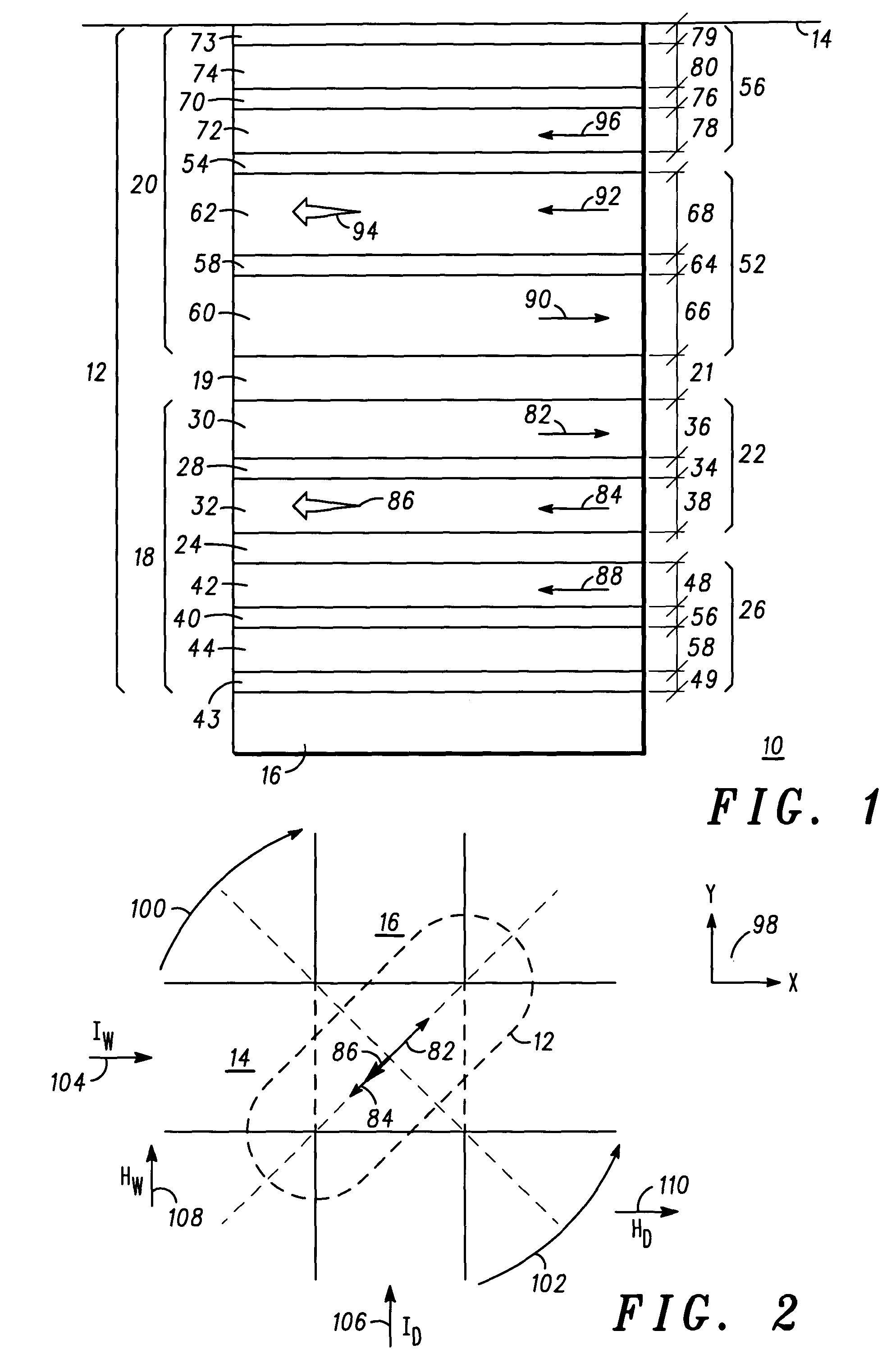
For bit 18, ferromagnetic layers 30 and 32 each have a magnetic moment vector 82 and 84, respectively, that are usually held anti-parallel by coupling of the anti-ferromagnetic coupling spacer layer 28. Also, magnetic region 22 has a resultant magnetic moment vector 86 and magnetic region 26 has a resultant magnetic moment vector 88. Resultant magnetic moment vectors 86 and 88 are oriented along an anisotropy easy-axis in a direction that is at an angle, preferably ...


PUM


Abstract

A method to switch a scalable magnetoresistive memory cell including the steps of providing a magnetoresistive memory device (12) having two bits (18) and (20) sandwiched between a word line (14) and a digit line (16) so that current waveforms (104) and (106) can be applied to the word and digit lines at various times to cause a magnetic field flux HW and HD to rotate the effective magnetic moment vectors (86) and (94) of the device (12) by approximately 180°. Each bit includes N ferromagnetic layers (32) and (34, 42) and (44, 60) and (62, 72 and 74) that are anti-ferromagnetically coupled. N can be adjusted to change the magnetic switching volume of the bit. One or both bits may be programmed by adjusting the current in the word and/or digit lines.

Description

FIELD OF INVENTION The present invention generally relates to magnetic random access memory (MRAM) memory. More particularly, the present invention relates to a method for writing a multi-state MRAM cell. BACKGROUND OF THE INVENTION Non-volatile memory devices are an extremely important component in electronic systems. FLASH is the major non-volatile memory device in use today. Typical non-volatile memory devices use charges trapped in a floating oxide layer to store information. Disadvantages of FLASH memory include high voltage requirements and slow program and erase times. Also, FLASH memory has a poor write endurance of 104-106 cycles before memory failure. In addition, to maintain reasonable data retention, the scaling of the gate oxide is restricted by the tunneling barrier seen by the electrons. Hence, FLASH memory is limited in the dimensions to which it can be scaled. To overcome these shortcomings, magnetic memory devices are being evaluated. One such device is the MRAM...

Claims


Application Information

Patent Timeline
Patent Type & Authority Applications(United States)
IPC IPC(8): G11C11/15G11C11/16G11C11/56
CPCG11C11/5607G11C11/16H01L27/105
Inventor ENGEL, BRADLEY N.SALTER, ERIC J.SLAUGHTER, JON M.
Owner EVERSPIN TECHNOLOGIES
Why Eureka
Try Eureka