Electronic safety system for the avoidance of an overspeed condition in the event of a shaft failure

a safety system and electronic technology, applied in the direction of rotors, instruments, vessel construction, etc., can solve the problems of aircraft damage, engine damage, and serious hazard to persons and materials, and achieve the effect of short shut-off times and low wear ra

Inactive Publication Date: 2005-03-03
ROLLS ROYCE DEUT LTD & CO KG
View PDF4 Cites 10 Cited by
  • Summary
  • Abstract
  • Description
  • Claims
  • Application Information

AI Technical Summary

Benefits of technology

[0009] In a broad aspect, the present invention provides a safety system for the detection of a shaft failure and for the interruption of the further supply of energy to the driving-side end of the shaft which, while having a low rate of wear and ensuring short shut-off times, combines functional reliability with modest demands in terms of design, assembly and space.

Problems solved by technology

In the event of a failure of a shaft, which has a driving side and a driven side, i.e. an energy-generating and an energy-consuming side, the driving side which is now detached from the energy-extracting driven side will, as a general problem, be accelerated considerably, this resulting in a serious hazard to persons and material.
Such an overspeed condition is particularly problematic where the respective shaft is part of a means of passenger transport, for example an aircraft powered by gas-turbine engines.
In an aircraft engine, the failure of the low-pressure turbine shaft, in particular, and the resultant uncontrolled speed increase of the driving side of the low-pressure turbine shaft connected to the low-pressure turbine rotor can lead to the destruction of the engine and damage of the aircraft, thus constituting a considerable danger to persons and property.
Generally, the known electronic safety systems of gas turbine engines are disadvantageous in that the time period until shut-off of the fuel supply is relatively long, this resulting in increased strength requirements on the low-pressure turbine blades in connection with a higher weight and higher costs.
High investment is also incurred by the required cooling or heat shielding of the sensors and the electric connections situated in the hot zone of the low-pressure turbine shaft.
Since the required angle of rotation between the turbine shaft and the reference shaft until release of the pre-loaded driver is relatively large, the time until shut-off of the fuel supply will be correspondingly long.

Method used


Image

  • Electronic safety system for the avoidance of an overspeed condition in the event of a shaft failure
  • Electronic safety system for the avoidance of an overspeed condition in the event of a shaft failure
  • Electronic safety system for the avoidance of an overspeed condition in the event of a shaft failure

Examples


Embodiment Construction

[0020] The detailed description below should be read in conjunction with the summary of the invention above.

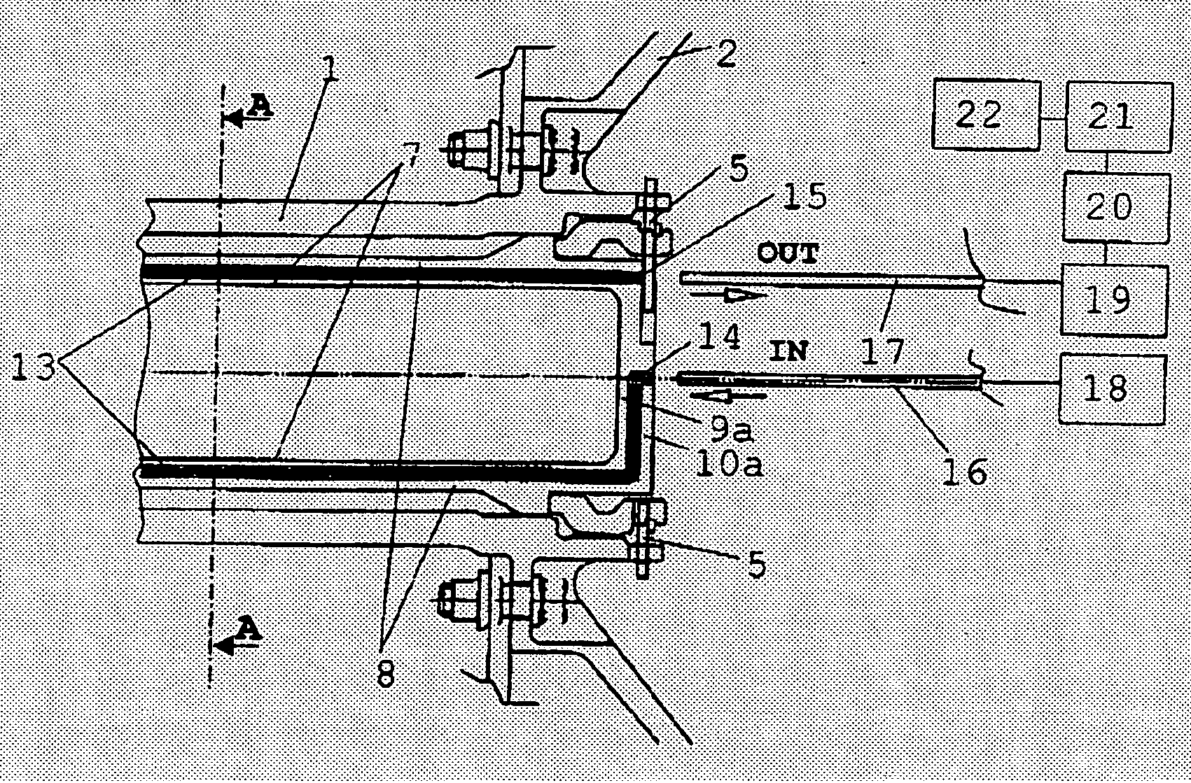
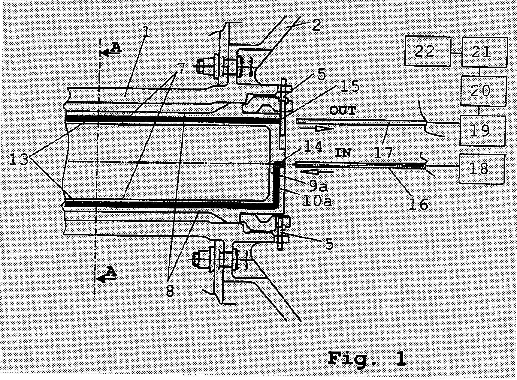
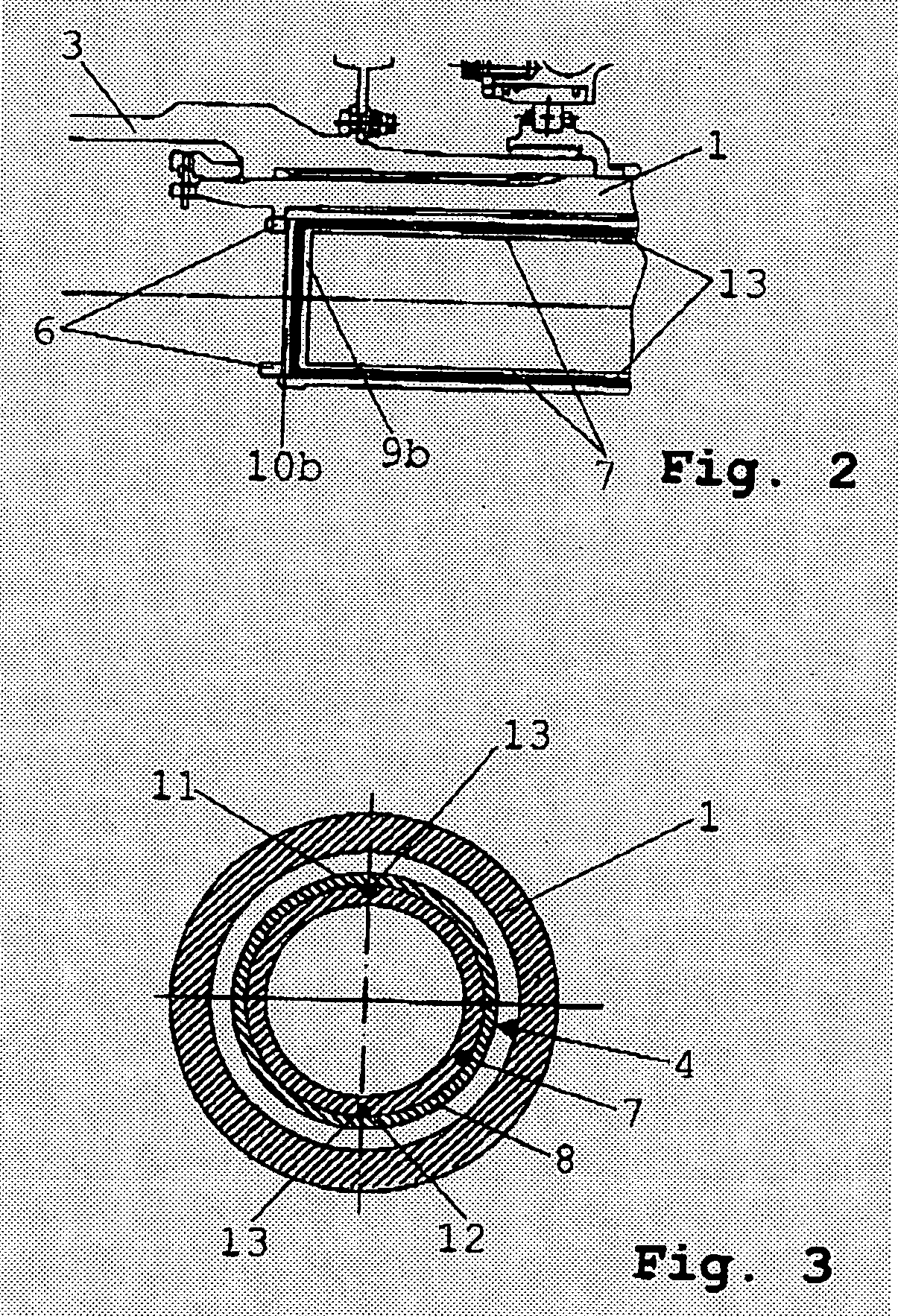
[0021] As indicated in FIGS. 1 and 3, the low-pressure turbine rotor 2 is attached to the driving side and the fan 3 (compressor) to the driven side of the low-pressure turbine shaft 1. Inside of the low-pressure turbine shaft 1, a coaxial measuring sleeve 4 is arranged which, at both ends, is firmly attached both circumferentially and axially to the low-pressure turbine shaft 1 by fasteners 5, 6, thus co-rotating with the shaft. The measuring sleeve 4 comprises an inner tube 7 and an outer tube 8 which are blanked at either end faces by a base plate 9a, b and 10a, b, respectively. In the outer circumference of the inner tube 7, two retaining grooves 11, 12 are provided which are opposite to each other and extend in the longitudinal direction of the measuring sleeve 4 and accommodate - flush with the surface of the inner tube 7—the measuring light guide 13. The outer tube (su...


PUM

PropertyMeasurementUnit
light transmissionaaaaaaaaaa
speedaaaaaaaaaa
strengthaaaaaaaaaa

Abstract

An electronic safety system for the detection of a shaft failure and for the interruption of the energy supply to the shaft includes at least one measuring light guide (13) which is firmly routed in the shaft longitudinal direction, co-rotates with the shaft (1) and is connected to a light source (18) on a light inlet side (14). In the event of a shaft failure, the measuring light guide will break to diminish light transmission therethrough, with the absence of light on a light outlet side (15) being detected by an optical sensor (19) and being used, via evaluation and control electronics (20, 21), as a signal for the shut-off of the further energy supply at a fuel shut-off valve (22). The measuring light guide is fixed to a measuring sleeve (4) attached at both ends to the shaft.

Description

[0001] This application claims priority to German Patent Application DE10310900.5 filed Mar. 13, 2003, the entirety of which is incorporated by reference herein. BACKGROUND OF THE INVENTION [0002] This invention relates to an electronic safety system for the avoidance of an overspeed condition in the event of a shaft failure by detection of the shaft failure and subsequent interruption of the further energy supply, in particular on a gas turbine engine. [0003] In the event of a failure of a shaft, which has a driving side and a driven side, i.e. an energy-generating and an energy-consuming side, the driving side which is now detached from the energy-extracting driven side will, as a general problem, be accelerated considerably, this resulting in a serious hazard to persons and material. Such an overspeed condition is particularly problematic where the respective shaft is part of a means of passenger transport, for example an aircraft powered by gas-turbine engines. In an aircraft en...

Claims


Application Information

Patent Timeline
Patent Type & Authority Applications(United States)
IPC IPC(8): F01D21/04
CPCF01D21/04F01D21/045F05D2270/091F05D2270/09F05D2300/614
Inventor RENSCH, DETLEF
Owner ROLLS ROYCE DEUT LTD & CO KG
Why Eureka
Try Eureka