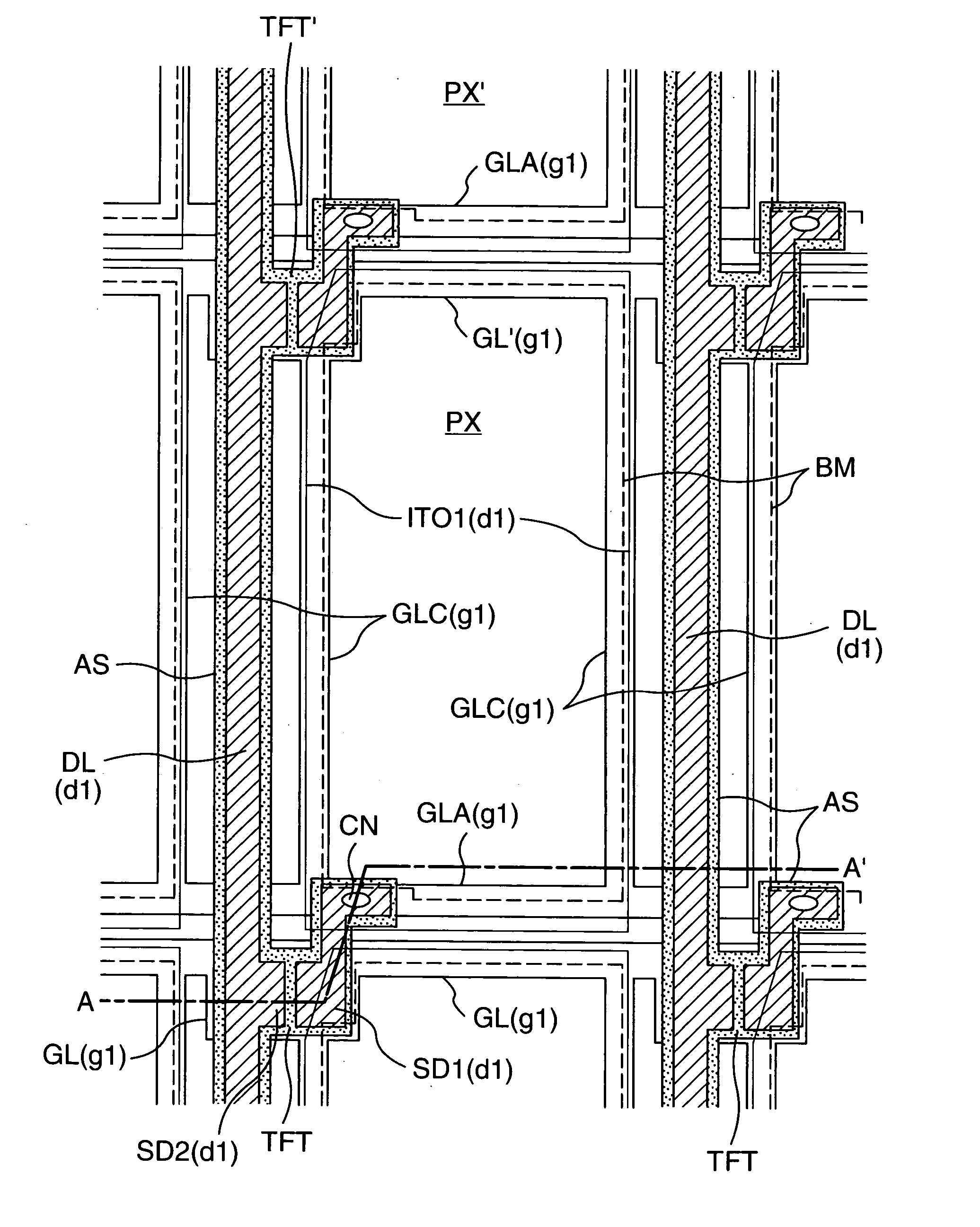
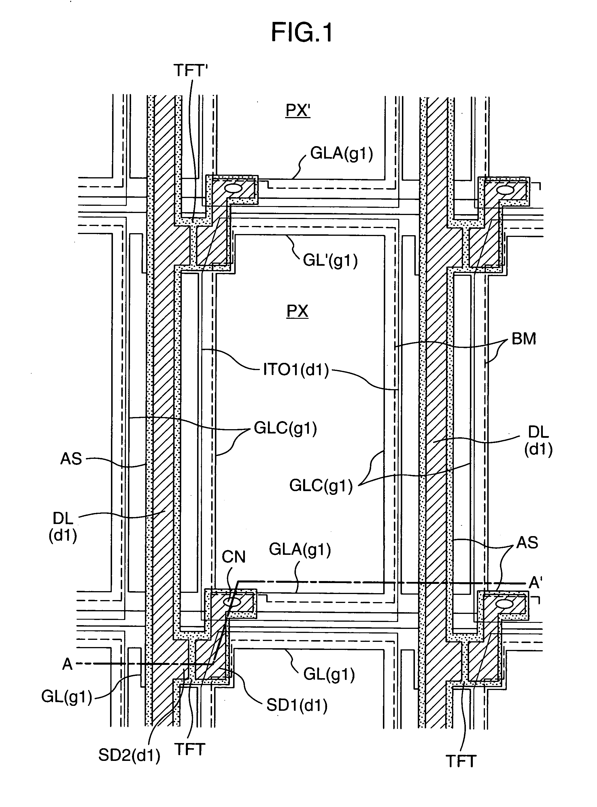
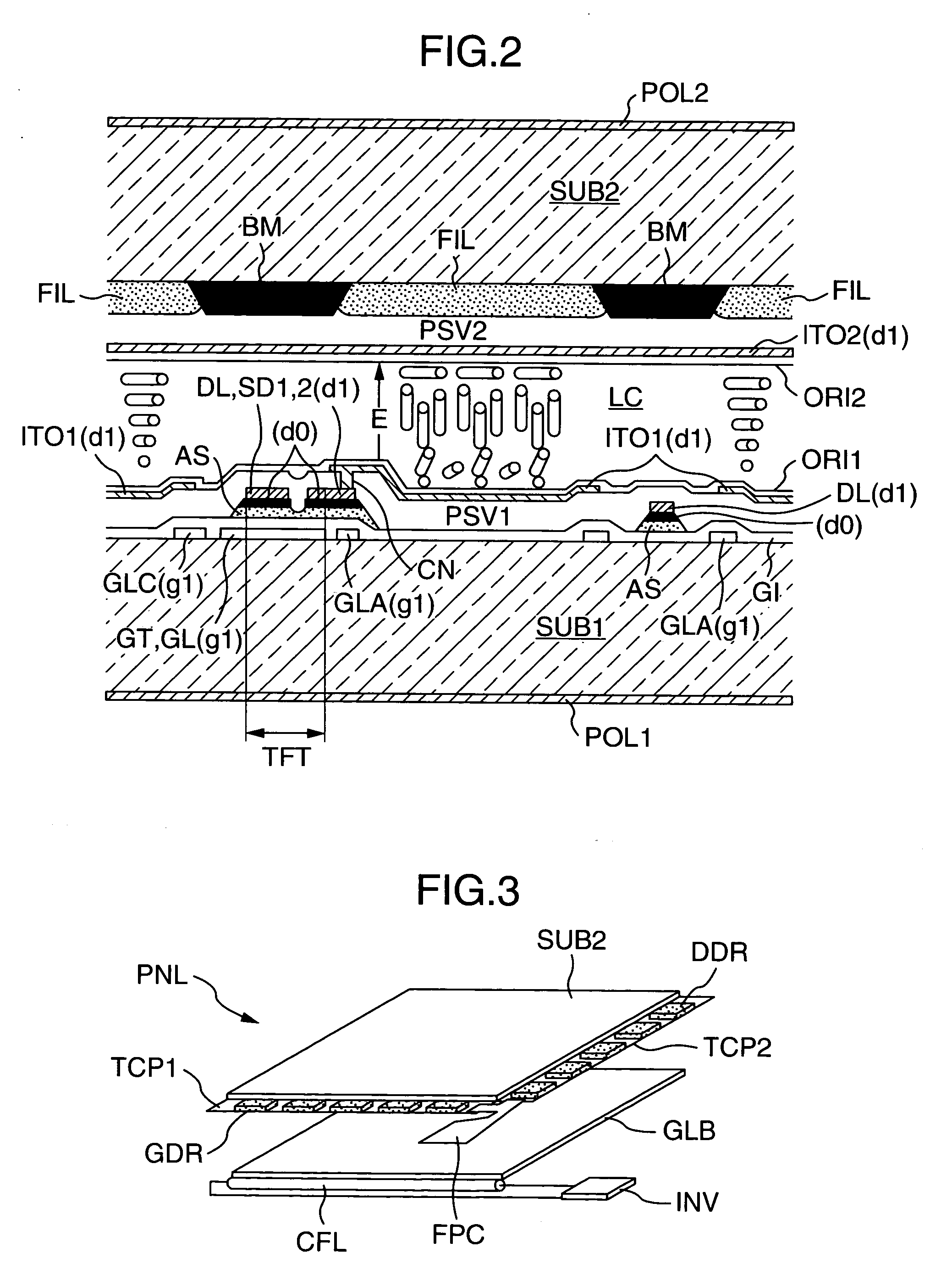
Colored composition for color filter and display using color filters formed of the colored composition

a color filter and composition technology, applied in the field of color filter composition for color filter and display using color filter formed of the colored composition, can solve the problems of increasing the production cost by increasing the number of steps, unavoidable use of pigment superior in light resistance in current color filter, and non-uniform display

Inactive Publication Date: 2005-03-03
PANASONIC LIQUID CRYSTAL DISPLAY CO LTD +1
View PDF10 Cites 18 Cited by
  • Summary
  • Abstract
  • Description
  • Claims
  • Application Information

AI Technical Summary

Benefits of technology

In order to achieve the above first object, the following colored composition for color filter is used in the present invention. That is, as a colored composition for color filter comprising at least one coloring agent, a base polymer and at least one solvent, there is used a colored composition for color filter containing as the

Problems solved by technology

However, a liquid crystal composition is contaminated in some cases with the dye owing to the diffusion of the dye itself into liquid crystals from the color filter, and the contamination causes nonuniform display.
Moreover, a color change caused by the photo-deterioration of the dye is fatal to the color filter, and a pigment superior in light resistance is unavoidably used in current color filters at the cost of contrast.
The technique disclosed in this reference, however, involves a pigment atomization step and only increases the production cost by increasing the number of steps.
However, in the case of the latent pigments, the dissolution of an acrylic resin as base polymer in a solvent is not sufficient.
This phenomenon of coloring causes a decrease in transmittance for blue color in a color filter and hence is a problem to be solved for realizing the improvement of the color filter in performance characteristics.
There are base polymers which are transp

Method used


Image

  • Colored composition for color filter and display using color filters formed of the colored composition
  • Colored composition for color filter and display using color filters formed of the colored composition
  • Colored composition for color filter and display using color filters formed of the colored composition

Examples


Embodiment Construction

Embodiments of the present invention are explained below in detail. At first, the constituents of the colored composition for color filter of the present invention, i.e., the base polymer, the coloring agent(s) and the solvent(s) are explained. The explanation is made with reference to the following structural formulas (3-1), (3-2) and (3-3):

A polyamicacid of the structural formula (3-3) used as the base polymer can be synthesized by ring-opening polyaddition of a tetracarboxylic acid dianhydride of the structural formula (3-1) and a diamine derivative of the structural formula (3-2). As the polyamicacid that is transparent in the visible region (wavelength: 400 nm to 800 nm), there can be exemplified polyamicacids obtained by the following combination: each of R2 in the structural formula (3-1) and R3 in the structural formula (3-2) is a linear aliphatic group or a cyclic aliphatic group.

The transparency of the base polymer in the visible region (wavelength: 400 nm to 800 nm)...


PUM

PropertyMeasurementUnit
Fractionaaaaaaaaaa
Nanoscale particle sizeaaaaaaaaaa

Abstract

An object of the present invention is to obtain color filters having a high contrast, a high color purity and an improved transmittance for blue color, and a display using the color filters. In the present invention, there is used a colored composition for color filter comprising at least one coloring agent, a base polymer and at least one solvent, said base polymer containing a polyamicacid whose light transmittance decreases by 2% or less in the visible region (wavelength: 400 nm to 800 nm).

Description

INCORPORATION BY REFERENCE The present application claims priority from Japanese application JP2003-209591 filed on Aug. 29, 2003, the content of which is hereby incorporated by reference into this application. BACKGROUND OF THE INVENTION The present invention relates to a colored composition for color filter which permits color display, and a display using color filters formed of the colored composition. As thin and light color displays, flat panel displays such as liquid crystal displays, organic light emission displays and plasma display panels have been put to practical use or are under study for their practical application. For example, the liquid crystal displays have already been put to practical use as devices which fundamentally comprise two glass substrates and a liquid crystal layer (a liquid crystal composition) held between them and display letters, figures, drawings, pictures and the like owing to electro-optical effects. As to the driving mode of the liquid crystal...

Claims


Application Information

Patent Timeline
IPC IPC(8): C09B1/00G02B5/20C09B5/48C09B5/62C09B7/02C09B19/02C09B47/10C09B47/16C09B47/26C09B48/00C09B57/00C09B57/04G02F1/1335H01L27/32H01L51/00H01L51/50H05B33/12
CPCC09B1/005Y10T428/10C09B5/62C09B7/02C09B19/02C09B47/16C09B47/26C09B48/00C09B57/004C09B57/04C09B68/443G02F1/133514H01L27/322H01L51/0078Y10T428/1041Y10T428/1036C09B5/48C09K2323/031C09K2323/03C09K2323/00H10K59/38H10K85/311G02F1/1335
Inventor ARAYA, KOTAROSASAKI, HIROSHITOMIOKA, YASUSHI
Owner PANASONIC LIQUID CRYSTAL DISPLAY CO LTD
Why Eureka
Try Eureka