Part load blade tip clearance control

a technology of blade tip clearance and part load, which is applied in the direction of machines/engines, turbine/propulsion fuel heating, mechanical equipment, etc., can solve the problems of limiting the load reduction which can be achieved, and the production of high levels of carbon monoxide (co) during combustion

Inactive Publication Date: 2005-03-10
SIEMENS ENERGY INC
View PDF18 Cites 63 Cited by
  • Summary
  • Abstract
  • Description
  • Claims
  • Application Information

AI Technical Summary

Benefits of technology

[0013] The substantially constant design temperature of the cooling air can be from about 350 degrees Fahrenheit to about 480 degrees Fahrenheit. Thus, the cooling circuit can reduce the temperature of

Problems solved by technology

Part load operation may result in the production of high levels of carbon monoxide (CO) during combustion.
It is critical to maintain a minimal blade tip clearance C sufficient enough that the blades

Method used


Image

  • Part load blade tip clearance control
  • Part load blade tip clearance control
  • Part load blade tip clearance control

Examples


Embodiment Construction

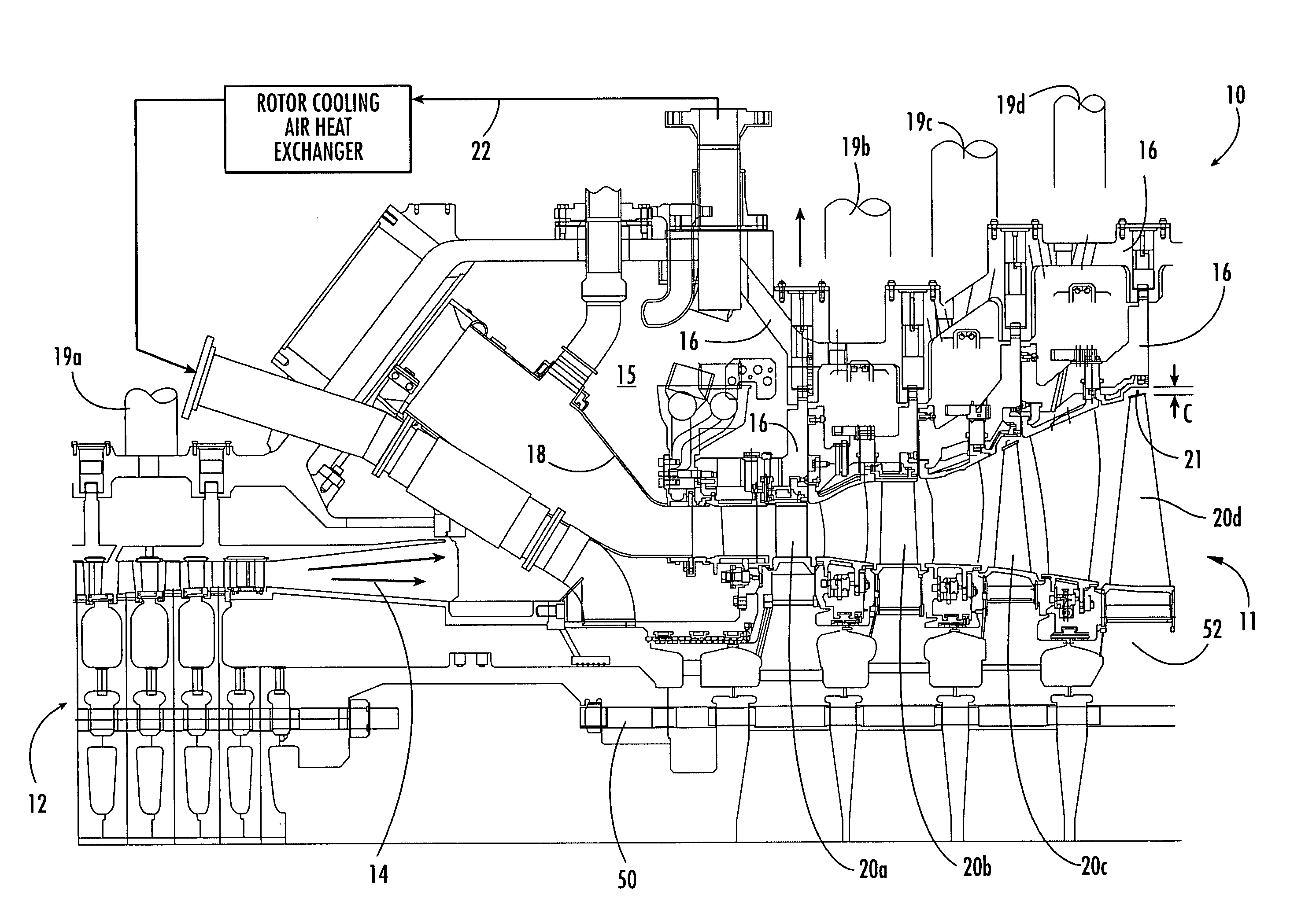
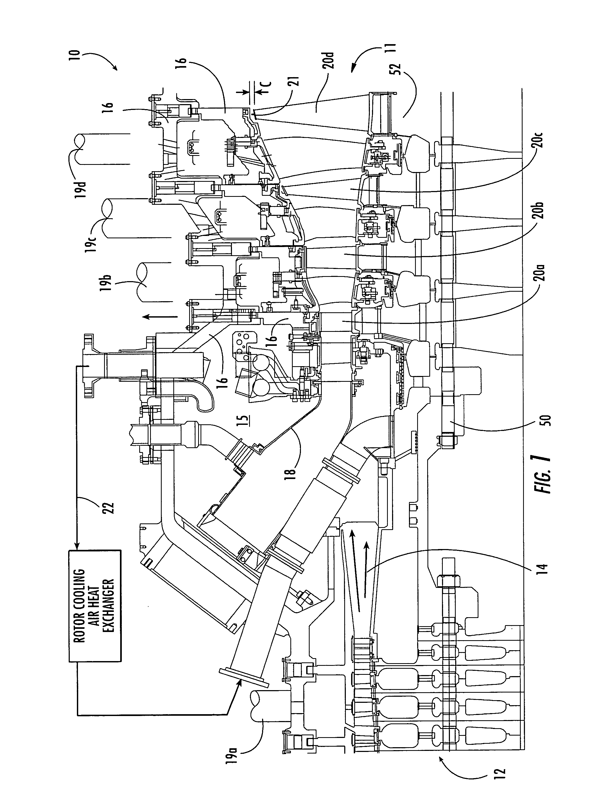
[0018] Aspects of the present invention address a blade tip clearance problem that can occur when the turbine inlet temperature is maintained at a high level during part load operation of a gas turbine, which may be done, for example, to reduce CO emissions. To that end, aspects of the present invention relate to a method for ensuring a minimum blade tip clearance under such conditions. Other aspects of the present invention relate to a turbine engine configuration for maintaining a blade tip clearance during part load operation.

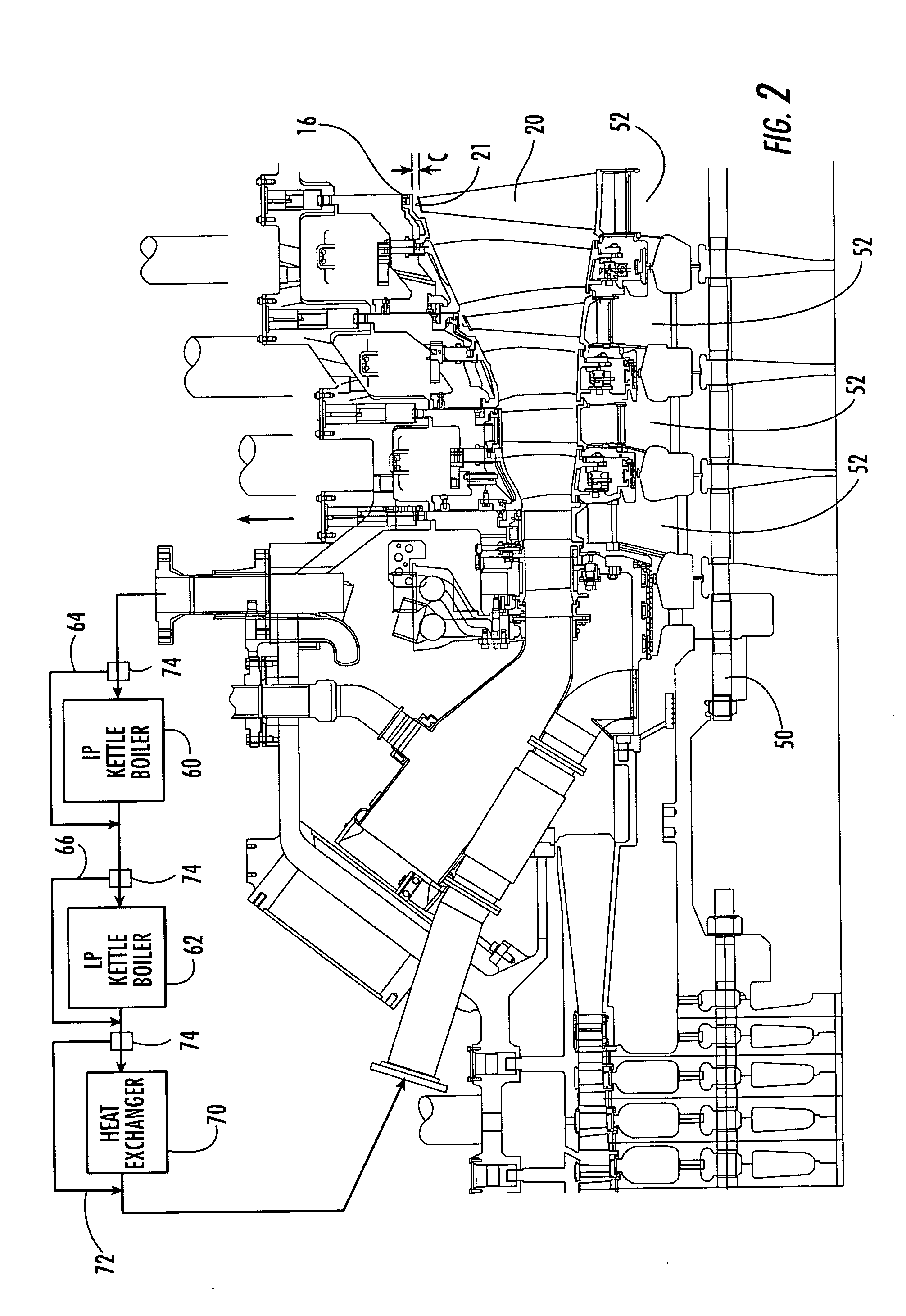
[0019] Embodiments according to aspects of the invention are shown in FIGS. 2-4, but the present invention is not limited to the illustrated structure or application. Further, the following detailed description is intended only as exemplary.

[0020] In some turbine engine designs, compressor exit air 14 from the combustor shell 15 can be used to cool at least the turbine rotor 50, discs 52, and blades 20. In such instances, the compressor exit air is routed ...


PUM


Abstract

Aspects of the invention relate to a turbine engine configuration and method for overcoming a turbine blade tip clearance problem that can arise when the turbine inlet temperature is maintained at a high level during part load operation of the turbine. Aspects of the invention relate to reducing rotor cooling air to a temperature below the design temperature level by using, for example, additional heat extraction devices or by reconfiguring or resizing existing heat exchanger devices. Upon exposure to the cooled air, the discs and blades of the turbine will shrink so as to provide a clearance between the blade tips and surrounding stationary support structure. The design rotor cooling air temperature can be from about 350 degrees Fahrenheit to about 480 degrees Fahrenheit. Aspects of the present invention can be used to decrease the rotor cooling air to about 150 degrees Fahrenheit at about 70 percent load.

Description

FIELD OF THE INVENTION [0001] The invention relates in general to turbine engines and, more particularly, to an apparatus and method for maintaining a minimum clearance between turbine blade tips and the surrounding turbine support structure under part load conditions. BACKGROUND OF THE INVENTION [0002] Turbine engines, such as single shaft industrial gas turbines, are designed to operate at a constant design turbine inlet temperature under any ambient air temperature (i.e., the compressor inlet temperature). This design turbine inlet temperature allows the engine to produce maximum possible power, known as base load. Any reduction from the maximum possible base load power is referred to as part load operation. In other words, part load entails all engine operation from 0% to 99.9% of base load power. [0003] Part load operation may result in the production of high levels of carbon monoxide (CO) during combustion. One known method for reducing part load CO emissions is to bring the c...

Claims


Application Information

Patent Timeline
IPC IPC(8): F01D5/08F01D11/24F02C7/18F02C7/224
CPCF01D5/08F01D5/085F02C7/224F02C7/185F01D11/24
Inventor LITTLE, DAVID ALLEN
Owner SIEMENS ENERGY INC
Why Eureka
Try Eureka