

Opto-acoustoelectric device and methods for analyzing mechanical vibration and sound
a technology of opto-acoustoelectric devices and mechanical vibration, applied in the direction of vibration measurement in solids, instruments, specific gravity measurement, etc., can solve the problems of reduced manufacturing yield, mechanical structure and dimensional constraints of the proposed methods, and reduced manufacturing yield due to an increase in constituents
- Summary
- Abstract
- Description
- Claims
- Application Information
AI Technical Summary
Benefits of technology
Problems solved by technology
Method used
Image

Examples
first embodiment
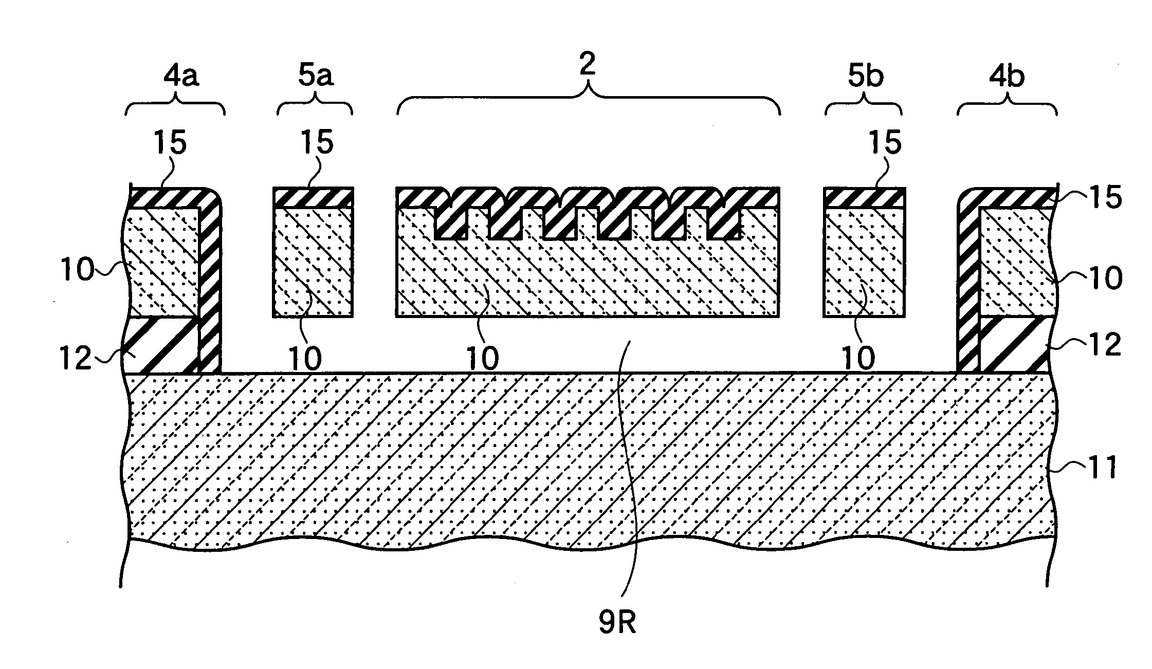
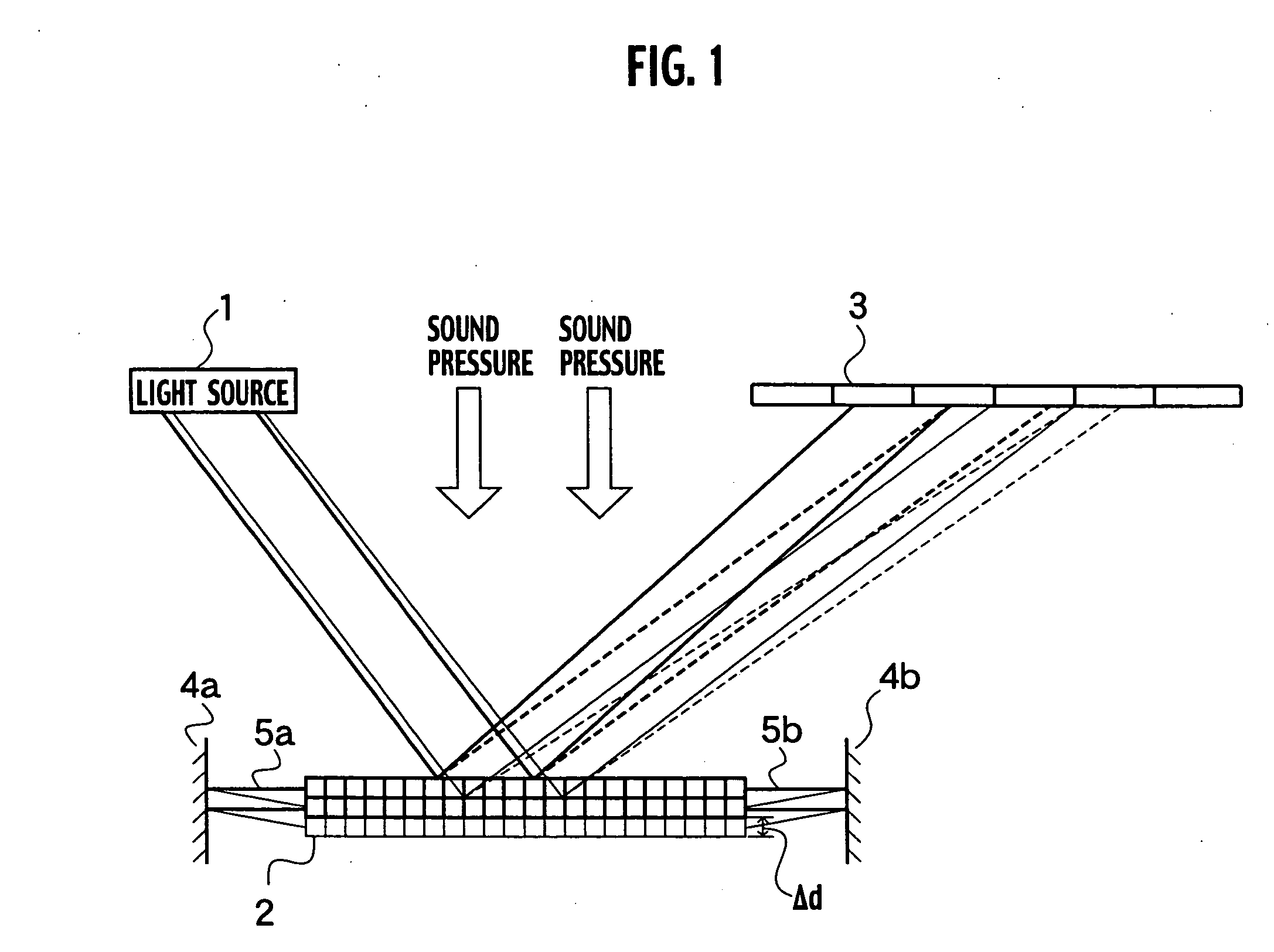
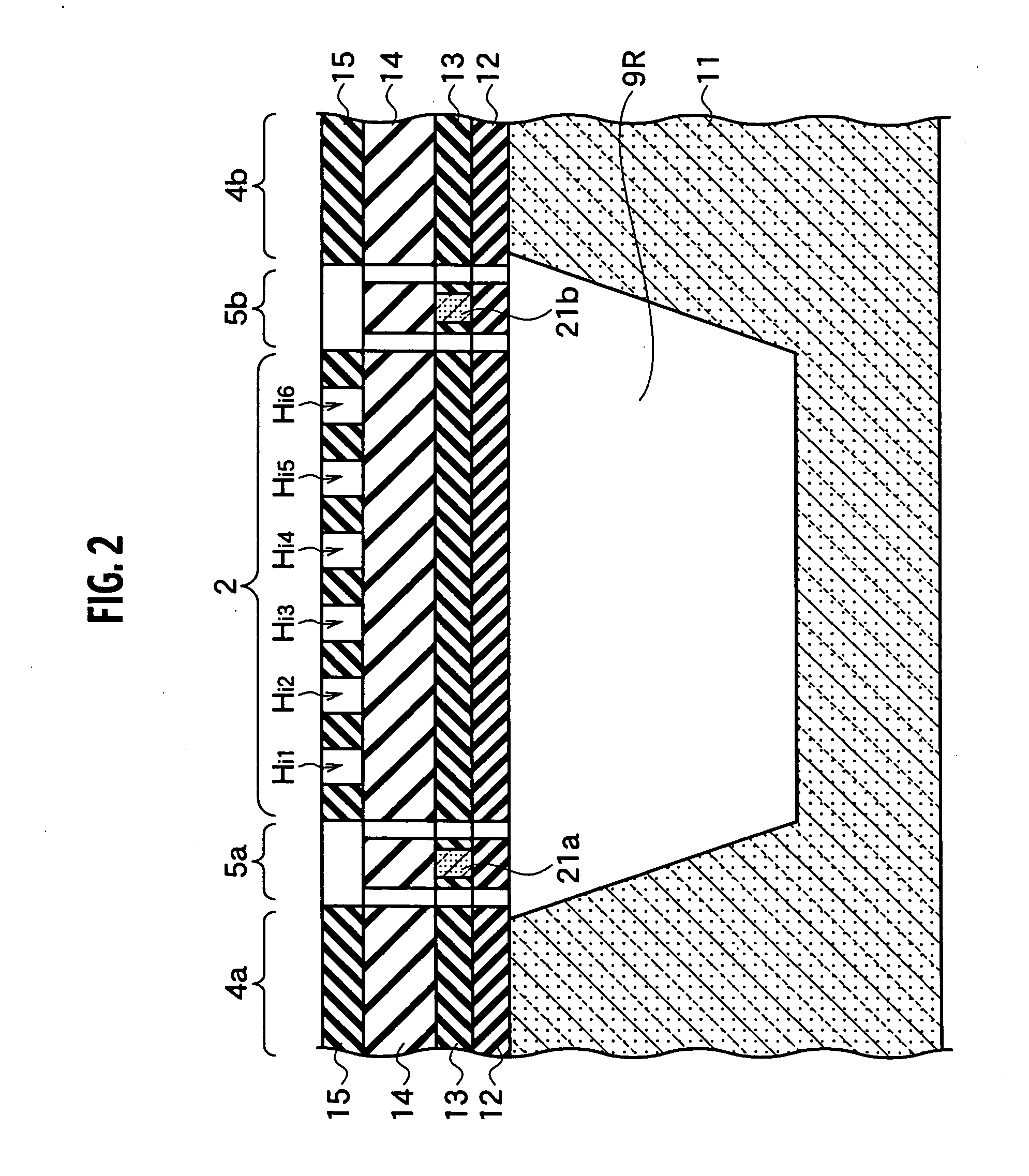
As illustrated in FIG. 1, an opto-acoustoelectric device according to a first embodiment of the present invention encompasses a mechanical vibration element implemented by a diaphragm 2, the diaphragm 2 has a diffraction grating that vibrates in response to sound pressure, a light source 1 configured to expose the diffraction grating to light, and a photo detector—3 configured to detect light diffracted by the diffraction grating and convert it into an electric signal.
It is preferable to use an image sensor such as a photo diode array etc. as the photo detector 3 illustrated in FIG. 1. Thus, the photo detector 3 is ensured a sufficiently wide area for diffracted light so that it is possible to fully and completely detect the diffraction image.
With the opto-acoustoelectric device according to the first embodiment, when light beamed from the light source 1 is incident upon the diaphragm 2, because a reflection-type diffraction grating is formed upon the diaphragm 2, light waves b...
second embodiment
As illustrated in FIG. 18, an opto-acoustoelectric device according to a second embodiment of the present invention encompasses a diaphragm 2 having a transmission-type diffraction grating that vibrates in response to sound pressure, a light source 1 configured to expose the diffraction grating to light, and a photo detector 3 configured to detect the light diffracted by the diffraction grating and convert it into an electric signal. A feature such that the transmission-type diffraction grating is formed onto the diaphragm 2 differs with the feature of the opto-acoustoelectric device according to the first embodiment. Another features such that the diaphragm 2 is suspended by elastic connectors 5a, 5b from immovable members 4a, 4b is identical to the features of the opto-acoustoelectric device according to the first embodiment.
In the same manner as in the first embodiment, it is desirable to use an image sensor such as a photo diode array for the photo detector 3 shown in FIG. 18...
third embodiment
As illustrated in FIG. 23, an opto-acoustoelectric device according to a third embodiment of the present invention encompasses a diaphragm 2 configured to vibrate with an external mechanical vibration, a light modulation unit 201 configured to modulate the intensity of light by a repetitive periodic signal and to beam the light onto the diaphragm 2, and a demodulation unit 202 configured to detect the light interacted with the vibration of the diaphragm 2, and to analyze the frequency of the mechanical vibration by demodulating with the repetitive periodic signal used as a synchronizing signal for demodulation. Not limited to a triangular wave or a rectangular wave, an arbitrary rippled waveform may be acceptable for the “repetitive periodic signal”, if the signal can manifest a repetitive periodic change.
Here, an explanation will be made to describe the situation where the light intensity xin (t) changes sinusoidally, as represented by the following Equation (7). In other words,...
PUM
 Abstract
Description
Claims
Application Information