High peak-power kilohertz laser system employing single-stage multi-pass amplification

a laser system and multi-pass technology, applied in the field of laser systems, can solve the problems of damage to the pumped gain medium, non-uniform beams with small “filaments, etc., and achieve the effects of increasing the peak output power and energy conversion efficiency, high repetition rate, and ultra-short pulse width

Inactive Publication Date: 2005-03-10
THE UNITED STATES AS REPRESENTED BY THE DEPARTMENT OF ENERGY
View PDF5 Cites 11 Cited by
  • Summary
  • Abstract
  • Description
  • Claims
  • Application Information

AI Technical Summary

Benefits of technology

[0017] It is a therefore a primary advantage of the present invention is to increase the levels of peak output power and energy conversion efficiency that can be produced by a single-stage laser pulse amplifier while maintaining the capability of achieving high repetition rate (in the kilohertz range) and ultra-short pulse width (e.g., approx. 20-25 fs). Peak output power is defined as the ratio of the pulse energy to the pulse duration.
[0018] It is a further advantage of the present invention to reduce the cost (both purchase cost and maintenance cost) of high peak power, kilohertz femtosecond lasers.
[0019] It is a yet further advantage of the present invention to improve the ease of manufacture of high peak power, kilohertz femtosecond lasers.
[0020] It is a still further advantage of the present invention to improve the ease of use and maintenance of high peak power, kilohertz femtosecond lasers.
[0021] Accordingly, the present invention employs single-stage, multi-pass amplification to produce ultra-short pulse widths characteristic of single-stage systems, power output levels greater than those of many multi-stage systems, and high-efficiency. This is accomplished by employing a very small “seed” beam diameter, ...

Problems solved by technology

During pre-amplification passes, slight non-uniformities of the gain medium and/or slight sub-millimeter scattering imperfections on optical surfaces can result...

Method used


Image

  • High peak-power kilohertz laser system employing single-stage multi-pass amplification
  • High peak-power kilohertz laser system employing single-stage multi-pass amplification
  • High peak-power kilohertz laser system employing single-stage multi-pass amplification

Examples


Embodiment Construction

[0036] In the detailed description that follows, identical components have been given the same reference numerals, regardless of whether they are shown in different embodiments of the present invention. To illustrate the present invention in a clear and concise manner, the drawings may not necessarily be to scale and certain features may be shown in somewhat schematic form.

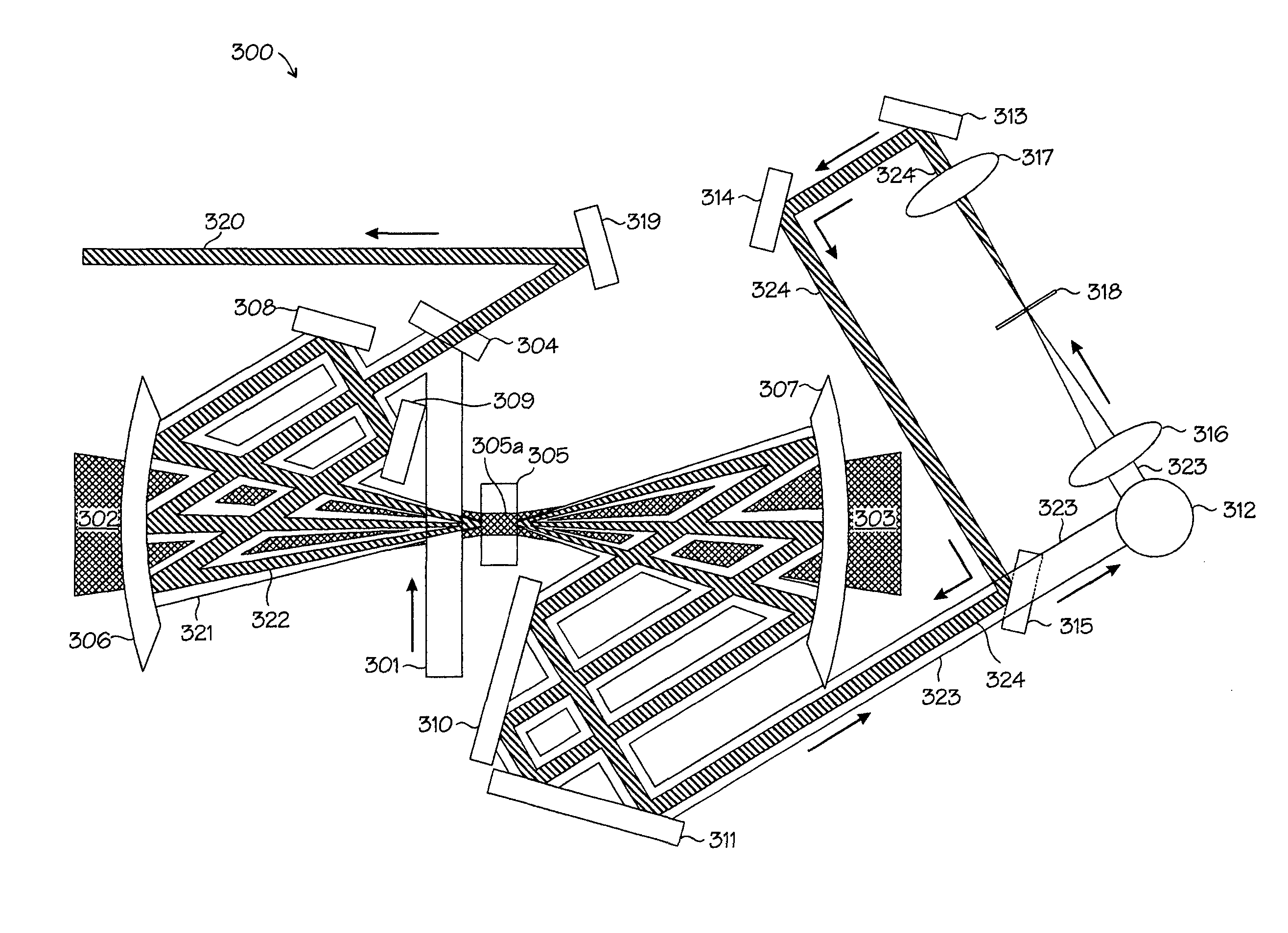
[0037] A primary object of the present invention is to increase the levels of peak output power and energy conversion efficiency that can be produced by a single-stage laser pulse amplifier while maintaining the capability of achieving high repetition rate and ultra-short pulse width (e.g., approx. 20-25 fs). Peak output power is defined as the ratio of the pulse energy to the pulse duration.

[0038] When compared to lasers of comparable power output and efficiency, a laser using a single-stage amplifier is cheaper, easier to manufacture and operate than those employing two or more stages of amplification.

[0039] ...


PUM


Abstract

The present invention describes a technique for achieving high peak power output in a laser employing single-stage, multi-pass amplification. High gain is achieved by employing a very small “seed” beam diameter in gain medium, and maintaining the small beam diameter for multiple high-gain pre-amplification passes through a pumped gain medium, then leading the beam out of the amplifier cavity, changing the beam diameter and sending it back to the amplifier cavity for additional, high-power amplification passes through the gain medium. In these power amplification passes, the beam diameter in gain medium is increased and carefully matched to the pump laser's beam diameter for high efficiency extraction of energy from the pumped gain medium. A method of “grooming” the beam by means of a far-field spatial filter in the process of changing the beam size within the single-stage amplifier is also described.

Description

GOVERNMENT SUPPORT [0001] This research was funded by Department of Energy grant no. DE-FG03-02ER15285 / A001.TECHNICAL FIELD [0002] The present invention relates generally to laser systems and more particularly to pulsed laser systems operating in the kilohertz (kHz) range of repetition rates. BACKGROUND ART [0003] Despite their relatively recent introduction, ultrafast (e.g., femtosecond-range pulse-width) high-intensity lasers are rapidly becoming important tools for both research and industry. Such laser systems are often referred to as “Ultrafast Kilohertz” lasers (or kHz lasers), referring to their pulse repetition rate in the kilohertz range, or as “femtosecond” (fs) lasers, referring to their very short pulse width, anywhere from tens to hundreds of femtoseconds (1 fs=10−15 seconds, or one one-thousandth of a picosecond). Only a little over decade after their invention, there are thousands of such lasers operating worldwide in research and industrial applications. [0004] New a...

Claims


Application Information

Patent Timeline
IPC IPC(8): H01S3/00H01S3/094H01S3/10H01S3/16H01S3/23
CPCH01S3/005H01S3/094038H01S3/2325H01S3/1636H01S3/1625
Inventor SHAN, BINGWANG, CHUNCHANG, ZENGHU
Owner THE UNITED STATES AS REPRESENTED BY THE DEPARTMENT OF ENERGY
Why Eureka
Try Eureka