Other system prescriptions with different lens specifications may be known to have better performance but be harder to manufacture.
However, none exist that could simultaneously satisfy all or even most of the desired specifications.
This keeps the optical mounting structure's connection to the base plate from being over constrained, potentially causing deformation with environmental changes, shock or vibration.
Yet, its complexity allows the other components to remain inexpensive and easy to construct.
Orientation: Spherical lens surfaces always engage well with a ring, which is unfortunately hard to provide with a topside only CNC mill post operation.
It is useful for as few as one lens and is only limited by the practical length of the Alignment Bolts.
As few as two posts have been successfully demonstrated, the upper limit is a matter of practicality.
An
assembly of these stages incorporated into the system design could provide the desired positioning tolerances but would have a prohibitive cost and a large physical
footprint.
Further, even with careful
engineering and costly components, such an
assembly would likely be too bulky with too many parts to be able to hold adjustment in the face of environmental changes such as temperature and vibration.
However, a 5 axis flexture stage that can meet the specifications set forth here might not actually be simple to construct nor inexpensive to manufacture.
One issue is how the flextures will be adjusted.
To achieve 1 um sensitivity requires the use of super-fine threads or possibly a
differential screw, both of which start driving up cost and require tight manufacturing tolerances.
Another issue is how these adjustments would be permanently locked without biasing the position and still allowing for
rework / disassembly.
Although this arrangement provides the desired degrees of adjustment, there are several drawbacks to this approach besides the cost and bulk of the two axis stages.
Finally, there are issues with the stability of such a configuration with environmental changes, especially during thermal
cycling.
However, the
adhesive will advantageously fail with the application of heat, e.g., with the aid of a
heat gun, allowing disassembly of the system for
rework or for fine-tuning of the system.
However, such a configuration might be more susceptible to environmental changes such as shock.
However, a thicker Mounting Plate will limit the angular positioning range, possibly forcing the use of a larger gap between the Mounting Plate and the Mounting Post.
In this case, the
mass of the detector
assembly could cause significant torque on the single
adhesive bond.
Therefore, such a configuration will be more susceptible to environmental changes such as shock.
The tradeoff is the limited
range of motion this configuration allows unless a very heavy application of clamping
adhesive (i.e. along with a larger
diameter thru hole) is allowed.
However, they do not allow repositioning of the detector once the adhesive clamp is cured without significant
rework effort.
Such dents would result in the system developing a “set” and reduce the ability to reposition with high precision.
Therefore, any dents would occur in the disposable sleeve.
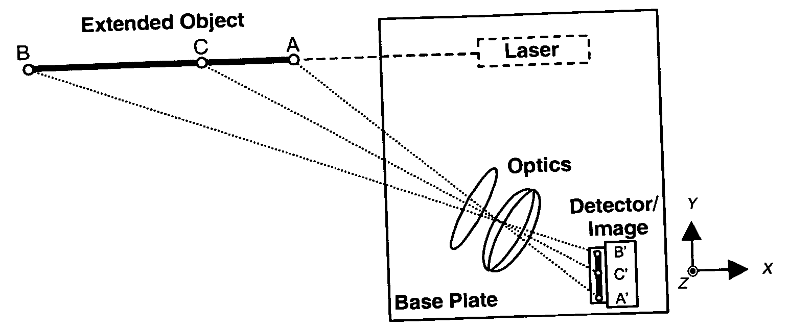
A system containing an unfolded
optics path, such as that shown in FIG. 1, would be larger than it needs to be and might present some difficulties in achieving alignment.

