Steerable bit assembly and methods

a technology of steering bit and assembly method, which is applied in the direction of drilling pipes, drilling rods, directional drilling, etc., can solve the problems of tilting in the washer face, and achieve the effect of reducing mechanical complexity, reducing drilling costs, and reducing drilling difficulty

Active Publication Date: 2005-03-17
BAKER HUGHES INC
View PDF11 Cites 152 Cited by
  • Summary
  • Abstract
  • Description
  • Claims
  • Application Information

AI Technical Summary

Benefits of technology

[0013] In one aspect, the present invention relates to systems, devices and methods for efficient and cost effective drilling of directional wellbores. The system includes a well tool such as a drilling assembly or a bottomhole assembly (“BHA”) at the bottom of a suitable umbilical such as drill string. The BHA includes a steering unit and a control unit. In embodiments, the steering unit and control unit provide dynamic control of bit orientation by utilizing fast response “smart” materials. In one embodiment, the control unit utilizes one or more selected measured parameters of interest in conjunction with instructions to determine a drilling direction for the BHA. The instructions can be either pre-programmed or updated during the course of drilling in response to measured parameters and optimization techniques. The control unit issues appropriate command signals to the steering unit. The steering unit includes one or more excitation field / signal generators and a “smart” material. In response to the command signal, the excitation signal / field generator produces an appropriate excitation signal / field (e.g., electrical or magnetic). The excitation signal / field causes a controlled material change (e.g., rheological, dimensional, etc.) in the “smart” material. The utilization of smart materials allows direct control rates that are faster and less mechanically complex than conventional rotary steerable directional systems.

Problems solved by technology

Varying the viscosity alters the distance a given piston shifts, which causes a tilt in the washer face.

Method used


Image

  • Steerable bit assembly and methods
  • Steerable bit assembly and methods
  • Steerable bit assembly and methods

Examples


Embodiment Construction

[0053] In one aspect, the present invention relates to devices and methods utilizing smart materials for steerable systems, devices and methods for drilling complex curvature directional wellbores. The present invention is susceptible to embodiments of different forms. There are shown in the drawings, and herein will be described in detail, specific embodiments of the present invention with the understanding that the present disclosure is to be considered an exemplification of the principles of the invention, and is not intended to limit the invention to that illustrated and described herein.

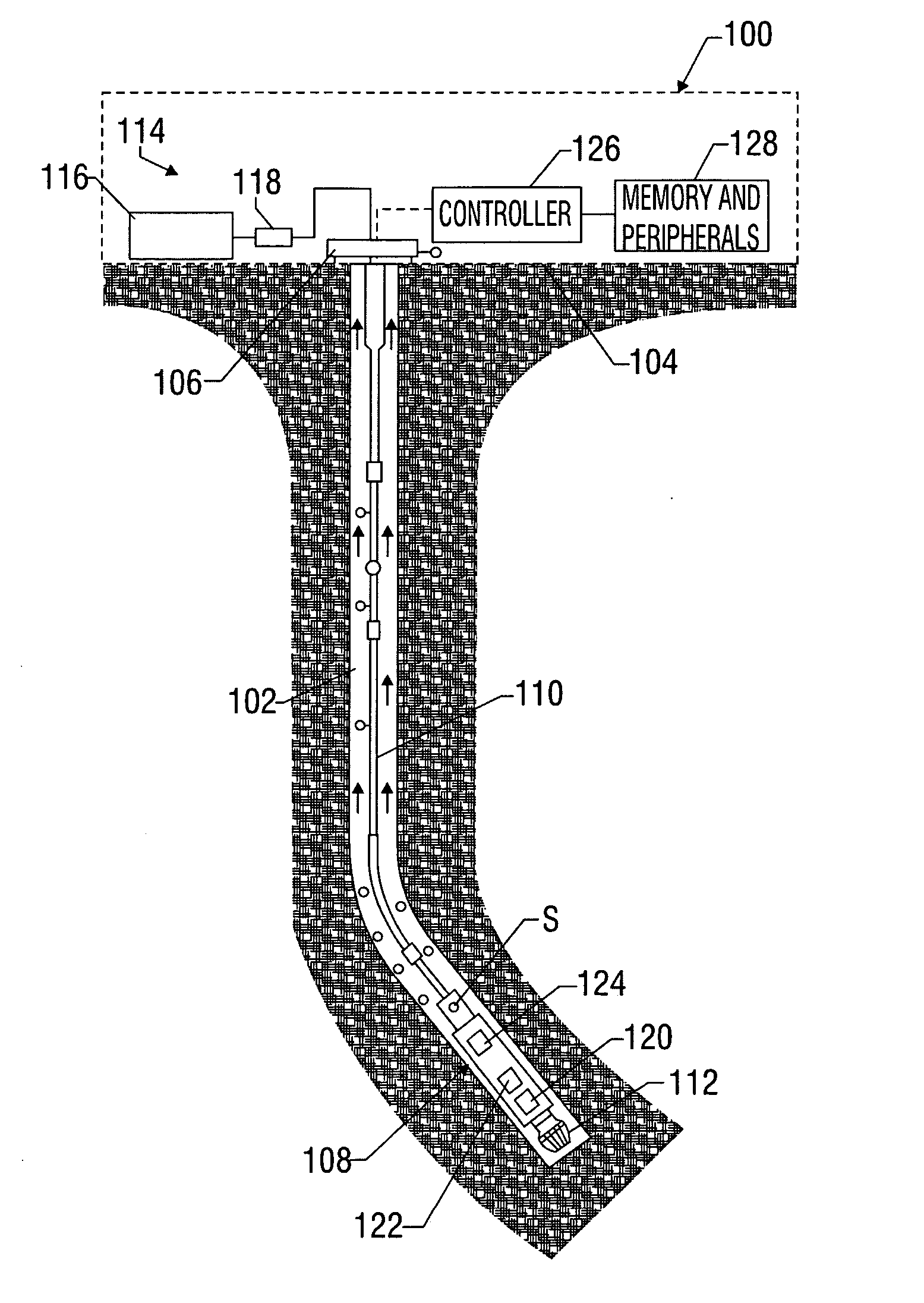
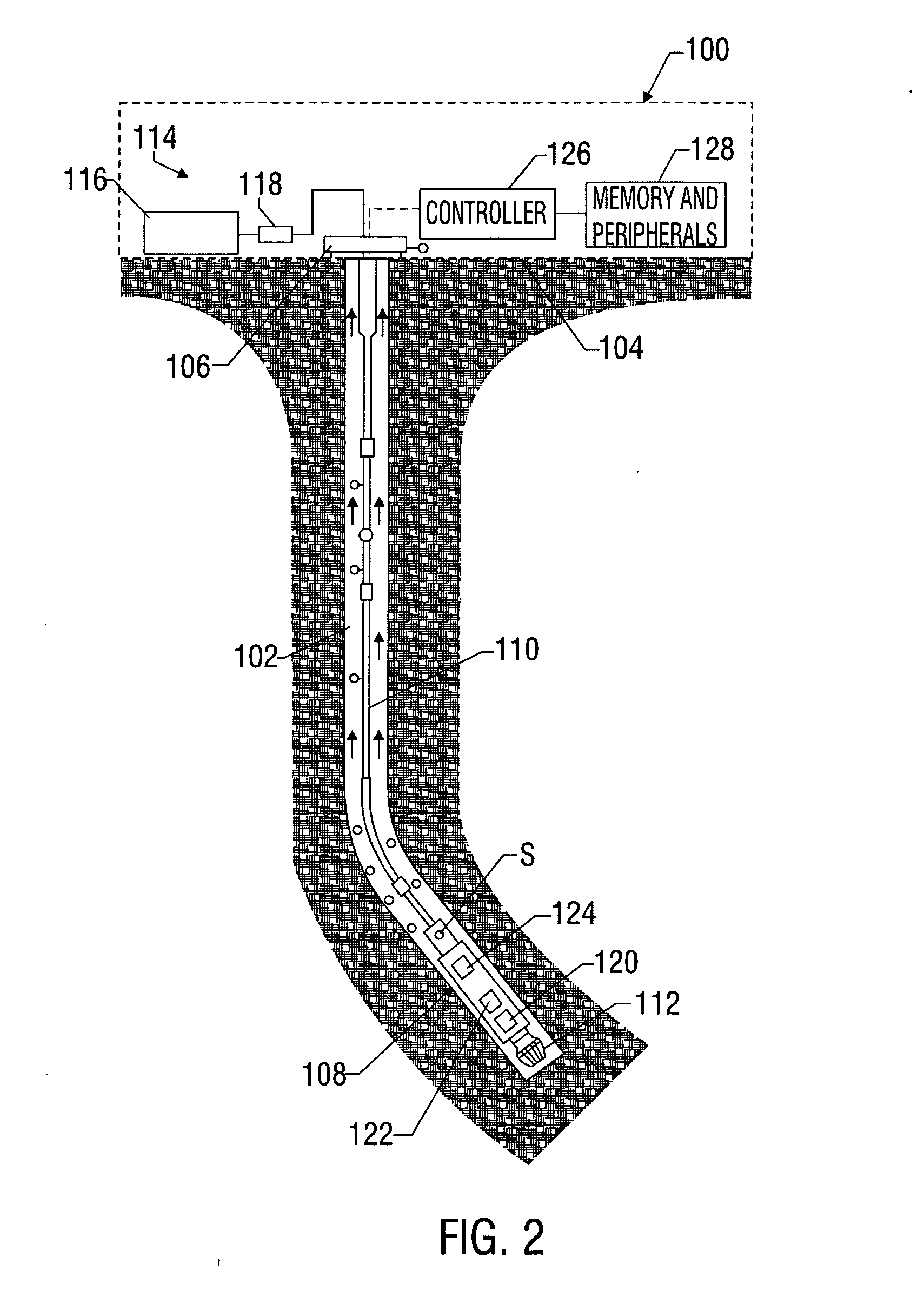
[0054] Referring initially to FIG. 2, there is schematically illustrated a system 100 for performing one or more operations related to the construction, logging, completion or work-over of a hydrocarbon producing well. In particular, FIG. 2 shows a schematic elevation view of one embodiment of a wellbore drilling system 100 for directionally drilling a wellbore 102. The drilling system 100 is a...


PUM


Abstract

A drilling system includes a steerable bottomhole assembly (BHA) having a steering unit and a control unit that provide dynamic control of drill bit orientation or tilt. Exemplary steering units can adjust bit orientation at a rate that approaches or exceeds the rotational speed of the drill string or drill bit, can include a dynamically adjustable articulated joint having a plurality of elements that deform in response to an excitation signal, can include adjustable independently rotatable rings for selectively tilting the bit, and/or can include a plurality of selectively extensible force pads. The force pads are actuated by a shape change material that deforms in response to an excitation signal. A method of directional drilling includes continuously cycling the position of the steering unit based upon the rotational speed of the drill string and/or drill bit and with reference to an external reference point.

Description

CROSS-REFERENCE TO RELATED APPLICATIONS [0001] This application takes priority from U.S. Provision Application No. 60 / 503,053 filed on Sep. 15, 2003.FIELD OF THE INVENTION [0002] In one aspect, this invention relates generally to systems and methods utilizing materials responsive to an excitation signal. In another aspect, the present invention relates to drilling systems that utilize directional drilling assemblies actuated by smart materials. In another aspect, the present invention related to systems and methods for producing fast response steerable systems for wellbore drilling assemblies. BACKGROUND OF THE ART [0003] To obtain hydrocarbons such as oil and gas, boreholes are drilled by rotating a drill bit attached at a drill string end. A large proportion of the current drilling activity involves directional drilling, i.e., drilling deviated and horizontal boreholes to place a wellbore as required, to increase the hydrocarbon production and / or to withdraw additional hydrocarbon...

Claims


Application Information

Patent Timeline
Patent Type & Authority Applications(United States)
IPC IPC(8): E21B7/06E21B10/60E21B10/61E21B10/62E21B17/10
CPCE21B7/062E21B7/067E21B17/1014E21B10/62E21B10/61
Inventor ARONSTAM, PETERFINCHER, ROGERWATKINS, LARRY
Owner BAKER HUGHES INC
Why Eureka
Try Eureka