Joint synchronizer and decoder

a synchronizer and decoder technology, applied in the field of digital signal processing techniques, can solve the problems of user terminals, unacceptable increase in transmission power of receivers, and increased cost of receivers, so as to reduce power level and cost, increase the likelihood of selecting, and reduce the signal-to-noise ratio

Active Publication Date: 2005-03-17
ADVANTECH SATELLITE NETWORKS
View PDF25 Cites 26 Cited by
  • Summary
  • Abstract
  • Description
  • Claims
  • Application Information

AI Technical Summary

Benefits of technology

[0022] The present invention meets the needs described above in a joint synchronizer and decoder (JSD) that elects among multiple candidates for a signal distortion parameter based on a measure of decoding success. This process, which is referred to as “decision aided candidate selection,” increases the likelihood of selecting the correct estimate of the signal distortion parameter when the signal-to-noise ratio declines to the point where the noise may mask the signal distortion parameter. As a

Problems solved by technology

However, increasing the transmission power of the receiver unacceptably increases the cost of the receiver.
The cost of the user terminal plays a major role in the business model of this type of services.
RF components of the terminals are costly.
Less expensive RF components result in tighter link budget on the uplink from the terminal to satellite.
As suggested above, numerous technical and physical problems complicate the synchronization in satellite communications.
For instance, the synchronization may be difficult where the transmitter and receiver are moving relative to each other.
Furthermore, varying weather conditions, such as clouds and rain, also affect the communication signals.
There is also certain level of inherent carrier frequency uncertainty at the transmitter output.
Overall, these and other conditions cause carrier frequency

Method used


Image

  • Joint synchronizer and decoder
  • Joint synchronizer and decoder
  • Joint synchronizer and decoder

Examples


Embodiment Construction

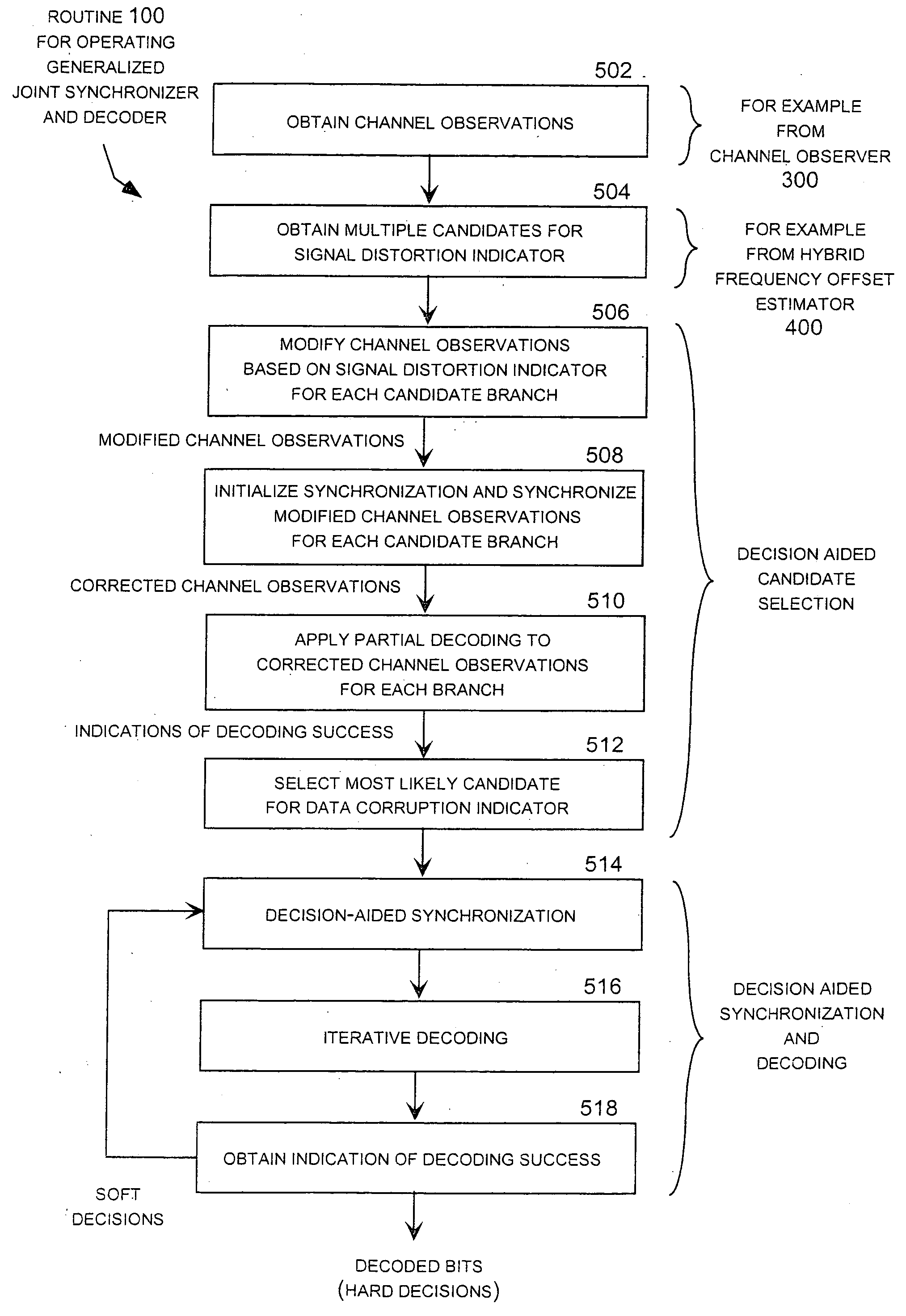
[0052] The main objective of the joint synchronizer and decoder (JDS) described below is to improve the power efficiency of burst-mode transmission of encoded data. Recent advancement in error correction coding techniques used over communication channels has made it possible to lower the transmitted power requirement to achieve a target performance for a given channel condition. Using schemes such as iterative decoding of turbo codes and Low Density Parity Check (LDPC) codes, the power requirements approach theoretical lower bounds established by channel capacity.

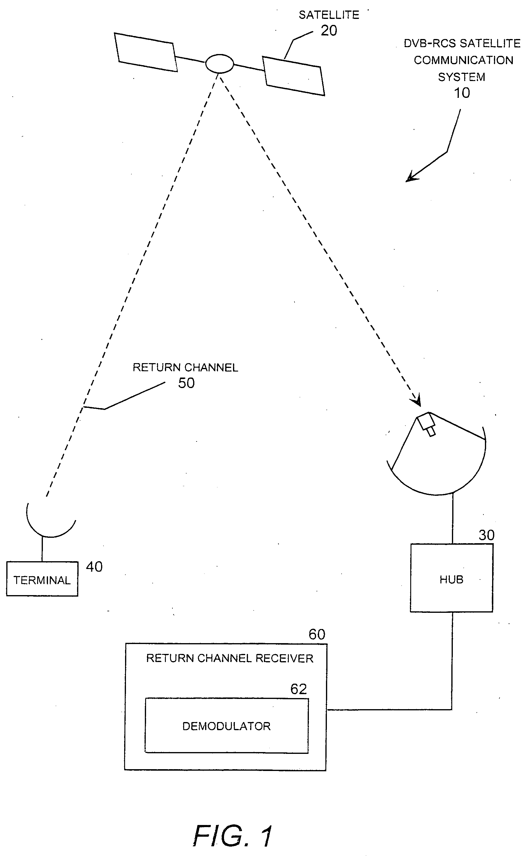
[0053] In a conventional coherent detection and decoding of encoded signal, it is essential to correct the channel observation for signal distortion, such as inter-symbol interference, carrier frequency offset, and phase noise prior to signal decoding. In particular, for burst-mode data transmission over satellite, the lack of accurate carrier frequency and phase synchronization can cause performance degradations that over...


PUM


Abstract

A joint synchronizer and decoder that implements two decision aided processes, which are referred to as “decision aided candidate selection” and “decision aided synchronization and decoding.” Decision aided candidate selection may be used to select a carrier frequency offset by selecting among a number of candidates for this parameter based on an indication of decoding success. Decision aided synchronization and decoding may be used for phase tracking based on an indication of decoding success. Although these joint synchronizing and decoding techniques may be implemented together, they may also be implemented independently. The joint synchronizer and decoder may be implemented within a return channel receiver in a DVB-RCS system using turbo coding and quadrature phase shift key (QPSK) data modulation.

Description

CROSS-REFERENCE TO RELATED APPLICATION [0001] This application claims priority to U.S. Provisional patent application Ser. No. 60 / 502,283 entitled “Joint Synchronization and Decoding of Burst Signals” filed on Sep. 12, 2003, the subject matter of which is incorporated by reference. This application is also related to and incorporates by reference U.S. patent application Ser. No.______ entitled “Hybrid Frequency Offset Estimator,” which is commonly owned and concurrently filed with the present application.TECHNICAL FIELD [0002] The present invention is directed generally to digital signal processing techniques for burst-mode data signals having short observation lengths in an environment experiencing a low signal-to-noise ratio (SNR). The invention is more particularly but not exclusively directed to a joint synchronizer and decoder (JSD) adapted for use in burst-mode phase shift key (PSK) modulation systems based on the Digital-Video Broadcast Return Channel via Satellite (DVB-RCS) ...

Claims


Application Information

Patent Timeline
IPC IPC(8): H04L27/00H04L27/22H04L27/233H04L27/26
CPCH04B7/18523H04L27/22H04L27/2657H04L27/2662H04L27/2695H04L2027/0046H04L2027/0065H04L27/2679H04L2027/0034
Inventor ALAGHA, NADER S.ERUP, LARS
Owner ADVANTECH SATELLITE NETWORKS
Why Eureka
Try Eureka