Clock and data recovery system for a wide range of bit rates

Inactive Publication Date: 2005-03-17
OPELCOMM
View PDF5 Cites 27 Cited by
  • Summary
  • Abstract
  • Description
  • Claims
  • Application Information

AI Technical Summary

Benefits of technology

[0011] An advantage of the present invention is that it permits bit rate transparency in serial optical communications.
[0012] Another advantage of the invention is that it is not necessarily limited to one fixed bit rate or to a few externally configurable fixed bit rates.
[0013] Another advantage of the invention is that it is that it does not require that the data rate be known and constant prior to clock recovery.
[0014] And another advantage of the invention is it is easily and ef

Problems solved by technology

While this presents no impediment to wire line communications, since the multitude of signaling standards there require

Method used


Image

  • Clock and data recovery system for a wide range of bit rates
  • Clock and data recovery system for a wide range of bit rates
  • Clock and data recovery system for a wide range of bit rates

Examples


Embodiment Construction

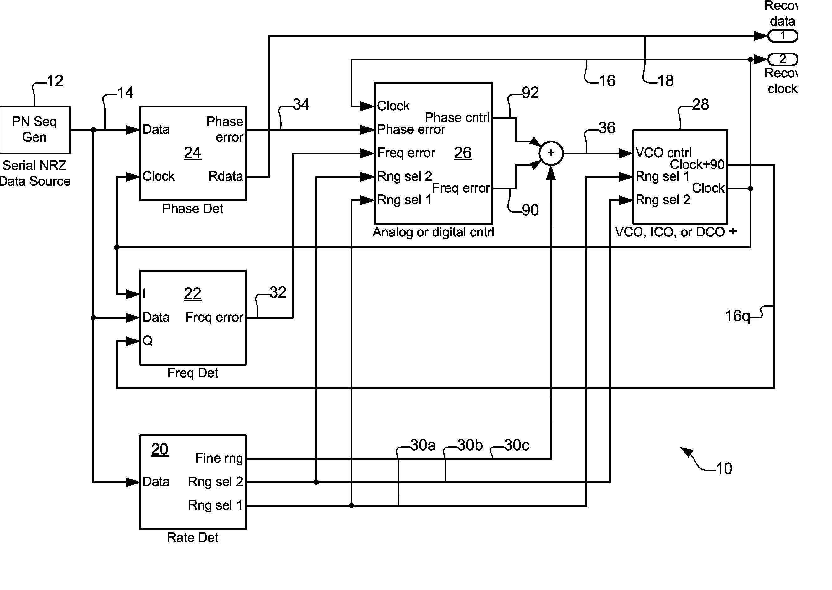
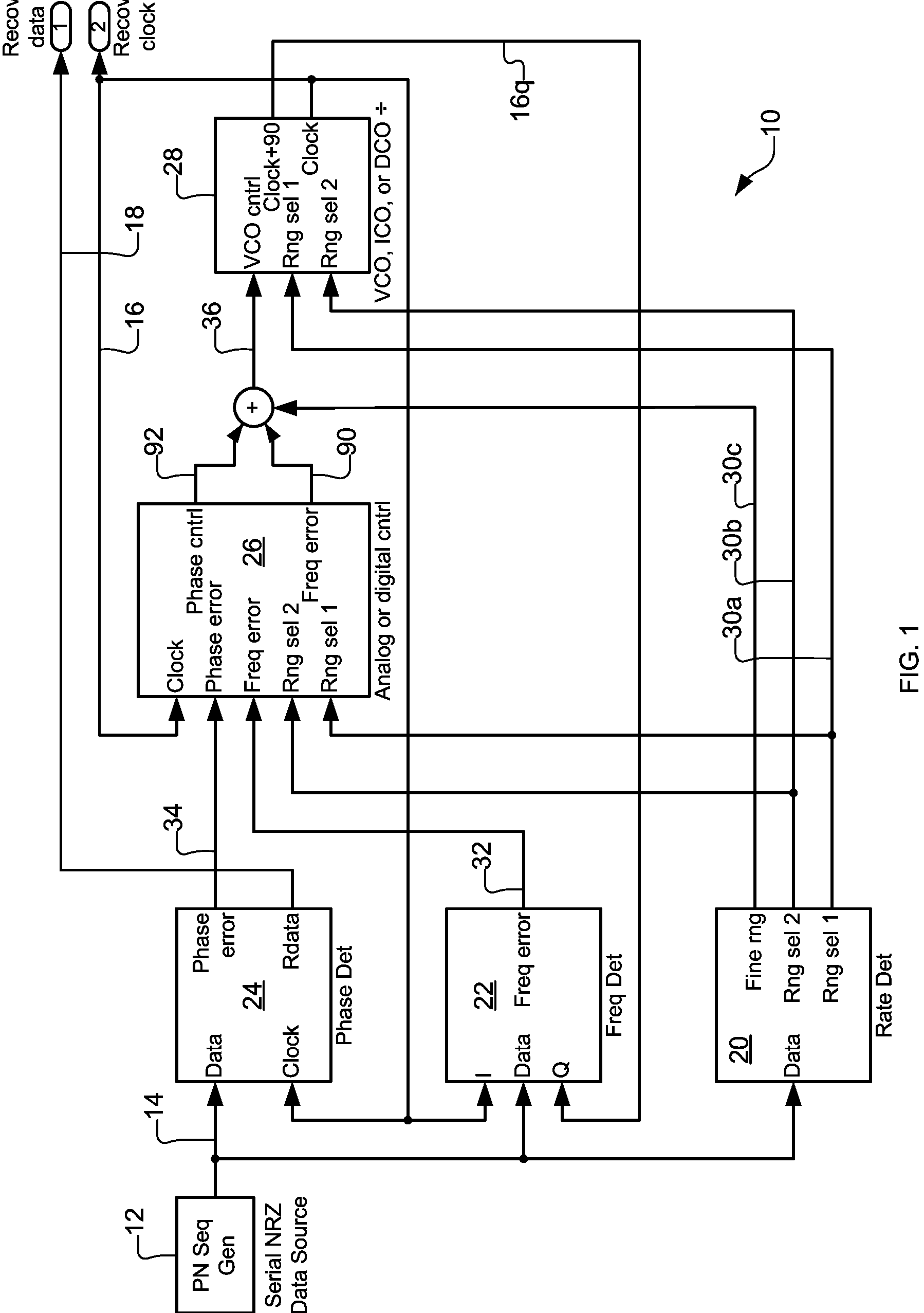
[0028] A preferred embodiment of the present invention is a clock and data recovery system suitable for use with a wide range of bit rates. As illustrated in the various drawings herein, and particularly in the view of FIG. 1, preferred embodiments of the invention are depicted by the general reference character 10.

[0029]FIG. 1 is a block diagram depicting an overview of a clock and data recovery circuit (CDR circuit 10) in accord with the present invention. The CDR circuit 10 works with a serial data source 12 that provides a source data signal 14, to ultimately obtain a recovered clock signal 16 and a recovered data signal 18. For this, the major components of the CDR circuit 10 include a rate detector 20, a frequency detector 22, a phase detector 24, a filter-controller 26, and an oscillator-divider 28.

[0030] Respectively, the rate detector 20, frequency detector 22, and phase detector 24 serve as first through third measurement sub-circuits. The task of the rate detector 20, a...


PUM


Abstract

A clock recovery system (10) for recovering an input data signal (14) clock. A rate detector (20) detects the input data signal bit rate and provides range signals (30a-c) specifying progressive ranges encompassing the bit rate. A frequency detector (22) provides a frequency error signal (32) based on frequency difference between the input data signal and a recovered clock signal (16). A phase detector (24) provides a phase error signal (34) based on the input data and recovered clock signals. A filter-controller (26) provides an oscillator driving signal (36) based on the range, frequency error, and phase error signals. An oscillator-divider (28) then provides the recovered clock signal based on the oscillator driving signal and at least some of the range signals. The phase detector, filter-controller, and oscillator-divider collectively thus form a phase locked loop. Optionally, the clock recovery system (10) may also provide a recovered data signal (18).

Description

CROSS REFERENCE TO RELATED APPLICATIONS [0001] This application claims the benefit of U.S. Provisional Application No. 60 / 481,391, filed Sep. 17, 2003.BACKGROUND OF INVENTION [0002] 1. Technical Field [0003] The present invention in general relates to optical data transmission systems, and in particular to devices and methods for recovering the timing information and data after an optical signal has been converted to an electronic signal. [0004] 2. Background Art [0005] Clock and data recovery (CDR) have long been performed on serial data transmissions to recover the timing information and the data at the receiving end of a serial line. Clock recovery for electrical wire line standards has unique conditioning standards that vary with the clock frequency. This results in the clock frequency or bit rate being known and being constant for the CDR devices used there. With the advent of optical communications methods, however, the large bandwidth and low loss of the fiber optic systems u...

Claims


Application Information

Patent Timeline
IPC IPC(8): H03D3/24H03D13/00H03L7/087H03L7/093H03L7/113H04BH04L7/033H04L25/02
CPCH03D13/004H03L7/087H04L25/0262H03L7/113H04L7/033H03L7/093
Inventor BEESON, DAVID A.CHAN, EDWARD S.L.
Owner OPELCOMM
Why Eureka
Try Eureka