Hermetic sealing of optical module

a technology of optical modules and hermetically sealed parts, applied in the field of optical modules, can solve the problems of increasing the complexity of telecommunication transmission systems, increasing the size and fragility of optical devices, and increasing the bandwidth of fiberoptic telecommunications

Inactive Publication Date: 2005-03-17
INTEL CORP
View PDF25 Cites 32 Cited by
  • Summary
  • Abstract
  • Description
  • Claims
  • Application Information

AI Technical Summary

Problems solved by technology

Optical devices are becoming increasingly smaller and more fragile.
In particular, fiberoptic telecommunications are continually subject to demand for increased bandwidth.
The advent of continuously tunable telecommunication lasers has introduced additional complexity to telecommunication transmission systems.
Particularly, the tuning aspects of such lasers involve multiple optical surfaces that are sensitive to contamination and degradation during use.
Lack of adequate protective packaging may decrease performance and lifetimes for such lasers.
Optoelectronics packaging is one of the most difficult and costly operations in optoelectronics manufacturing.
Process manufacturing demands like submicron alignment between optical elements, high-speed electrical connections, excellent heat dissipation, and high reliability become true challenges.
Providing such features has resulted in optoelectronic packages that may be larger, costlier and more difficult to manufacture than electronic packages.
In the case of an optoelectronic modules, it is difficult to align the laser diode with the optical lens or fiber when constructing the package.
Current designs use numerous parts in complex three-dimensional arrangements and generally need high degree of accuracy and automation.
Alignment of the fiber into the closed package may be challenging.

Method used


Image

  • Hermetic sealing of optical module
  • Hermetic sealing of optical module
  • Hermetic sealing of optical module

Examples


Embodiment Construction

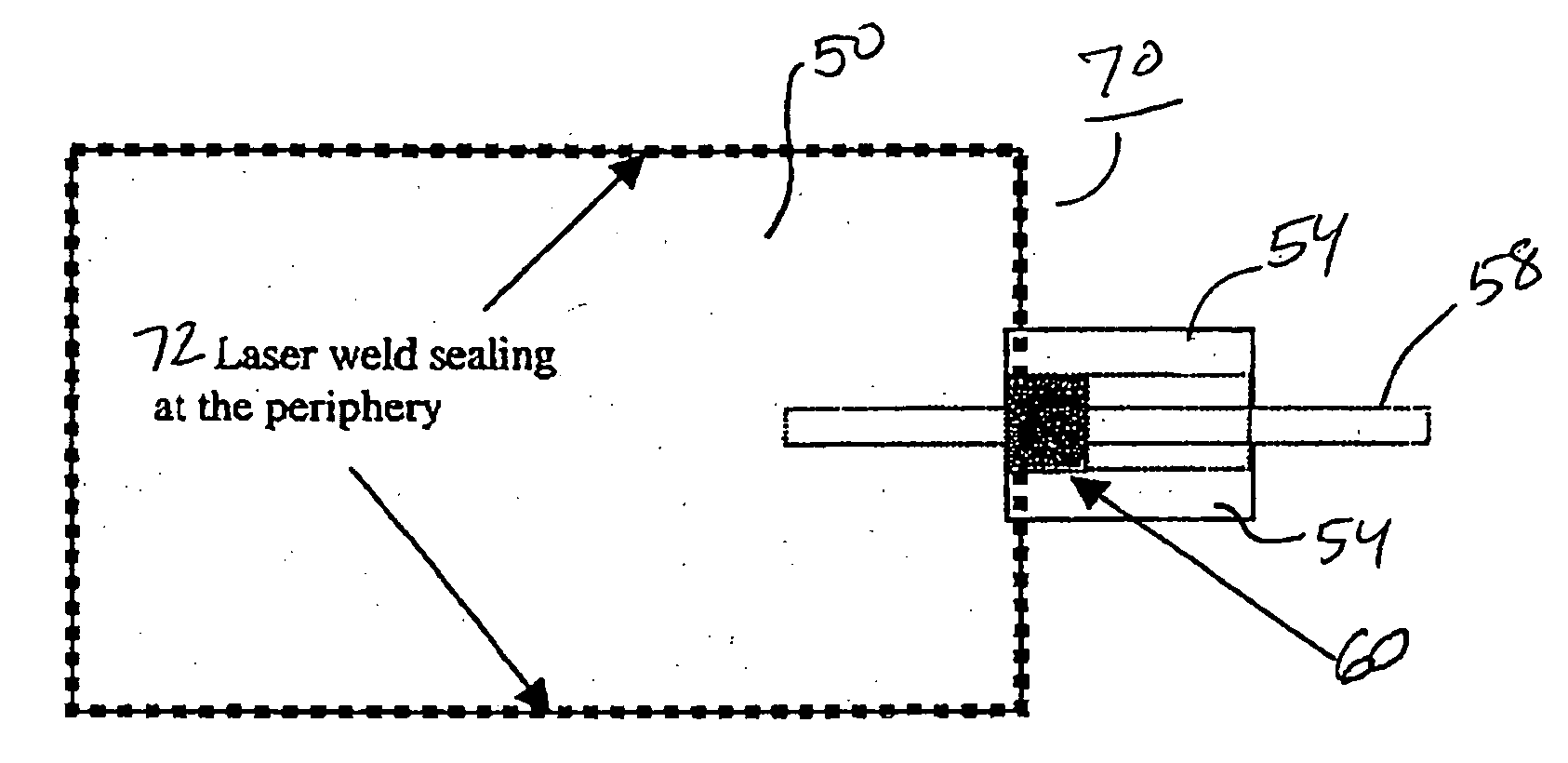
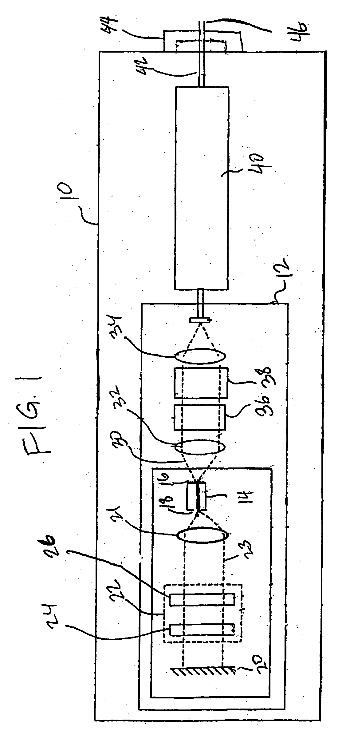
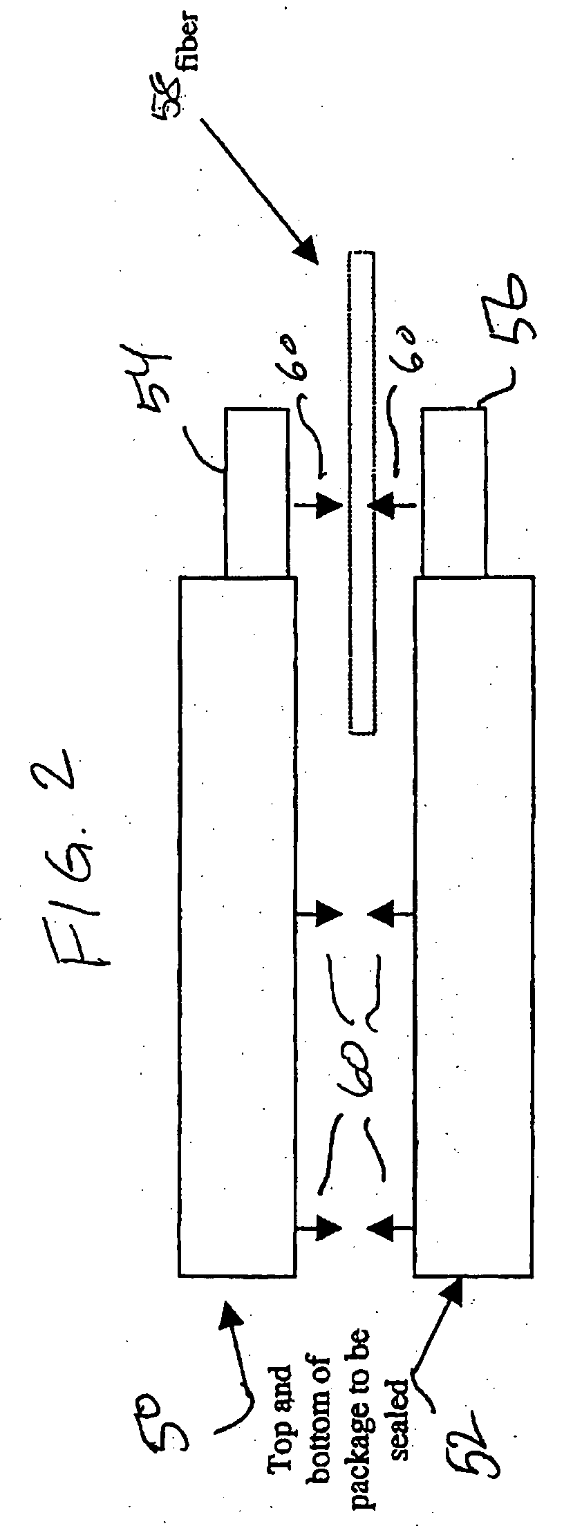
[0026] Embodiments of the invention provide hermetically sealed containers for use optical and opto-electrical modules or packages such as those used in laser systems. In its most general terms, such packages comprise an external cavity laser, and a hermetically sealable container configured to enclose the external cavity laser in an inert atmosphere thus protecting the contents from moisture and other contaminants.

[0027] In the following description, numerous specific details are set forth to provide a thorough understanding of embodiments of the invention. One skilled in the relevant art will recognize, however, that the invention can be practiced without one or more of the specific details, or with other methods, components, materials, etc. In other instances, well-known structures, materials, or operations are not shown or described in detail to avoid obscuring aspects of the invention.

[0028] Reference throughout this specification to “one embodiment” or “an embodiment” means ...


PUM


Abstract

A hermetically sealable package may be formed from a top portion and a bottom portion mated along a seam at or near a plane of an optical fiber. A completed pill assembly may be positioned directly into the enclosure base without requiring the fiber to be threaded through the feed through or “snout”. The top potion may then be mated with the bottom portion to form the package. A glass solder ring may be placed coaxial with the fiber in the feed through. The seam may be sealed by laser welding and the glass solder ring reflowed by laser heating, for example, with a same laser as used to weld the seam or by resistive or induction heating. In some embodiments a coupling tube around the fiber and snout or the snout itself may have holes to allow solder sealing within the snout and filling the remaining area with epoxy. Since the package is initially split in two pieces, module assembly may be facilitated without threading.

Description

FIELD OF THE INVENTION [0001] An embodiment of the present invention relates to optical modules and, more particularly, to hermetically sealed optical modules. BACKGROUND INFORMATION [0002] Fiber optics are used for a great number of applications. Everything from communication and computing systems, test and measurement systems, and medical systems and devices make use of optical technology. Optical devices are becoming increasingly smaller and more fragile. [0003] In particular, fiberoptic telecommunications are continually subject to demand for increased bandwidth. One way that bandwidth expansion has been accomplished is through dense wavelength division multiplexing (DWDM) wherein multiple separate data streams exist concurrently in a single optical fiber, with modulation of each data stream occurring on a different channel. Each data stream is modulated onto the output beam of a corresponding semiconductor transmitter laser operating at a specific channel wavelength, and the mo...

Claims


Application Information

Patent Timeline
Patent Type & Authority Applications(United States)
IPC IPC(8): G02B6/42
CPCG02B6/4248G02B6/4201G02B6/4251G02B6/4265G02B6/4267G02B6/4271
Inventor FINOT, MARC A.LAKE, RICKIE C.
Owner INTEL CORP
Why Eureka
Try Eureka