
Perpendicular magnetic recording medium and manufacturing of the same

Inactive Publication Date: 2005-03-17
HITACHI LTD
View PDF3 Cites 27 Cited by
  • Summary
  • Abstract
  • Description
  • Claims
  • Application Information

AI Technical Summary

Benefits of technology

[0018] Under such circumstances, it is an object of the present invention to realize a high media S / N value without degrading the magnetic isolation of crystal grains from each another. Such a high media S / N value is realized by promoting the magnetic isolation of crystal grains and reducing of crystal grain size.
[0021] The perpendicular magnetic recording medium formed as described above has crystallo graphic orientation improved enough without increasing the crystal grain size in the magnetic recording layer, so that the medium comes to be provided with a high S / N value.
[0024] According to the method for manufacturing the perpendicular magnetic recording medium configured as described above, the crystallo graphic orientation is improved enough while suppressing the crystal grain size in the magnetic recording layer, thereby enabling high S / N perpendicular magnetic recording media to be manufactured.
[0025] According to the present invention, therefore, a high medium S / N value is realized by improving the crystallo graphic orientation while suppressing the crystal grain size without degrading the magnetic isolation of crystal grains from each another. Furthermore, the crystal grain isolation is promoted and the crystal grains are miniaturized more while the crystallo graphic orientation is improved, thereby realizing a high medium S / N value.

Problems solved by technology

As the areal density increases, however, a so-called thermal decay problem has begun to arise remarkably.
Consequently, it has been considered to be very difficult to go over an areal density of 15.5 gigabits per square centimeter.
However, the method cannot obtain sufficient crystallo graphic orientation, so that the method might not be so effective to achieve a high S / N value.
However, at that time, the crystallo graphic orientation is degraded due to the promotion of the magnetic isolation of the crystal grains, so that the method might also not be so effective to achieve a high S / N value.

Method used


Image

  • Perpendicular magnetic recording medium and manufacturing of the same
  • Perpendicular magnetic recording medium and manufacturing of the same
  • Perpendicular magnetic recording medium and manufacturing of the same

Examples


example 1

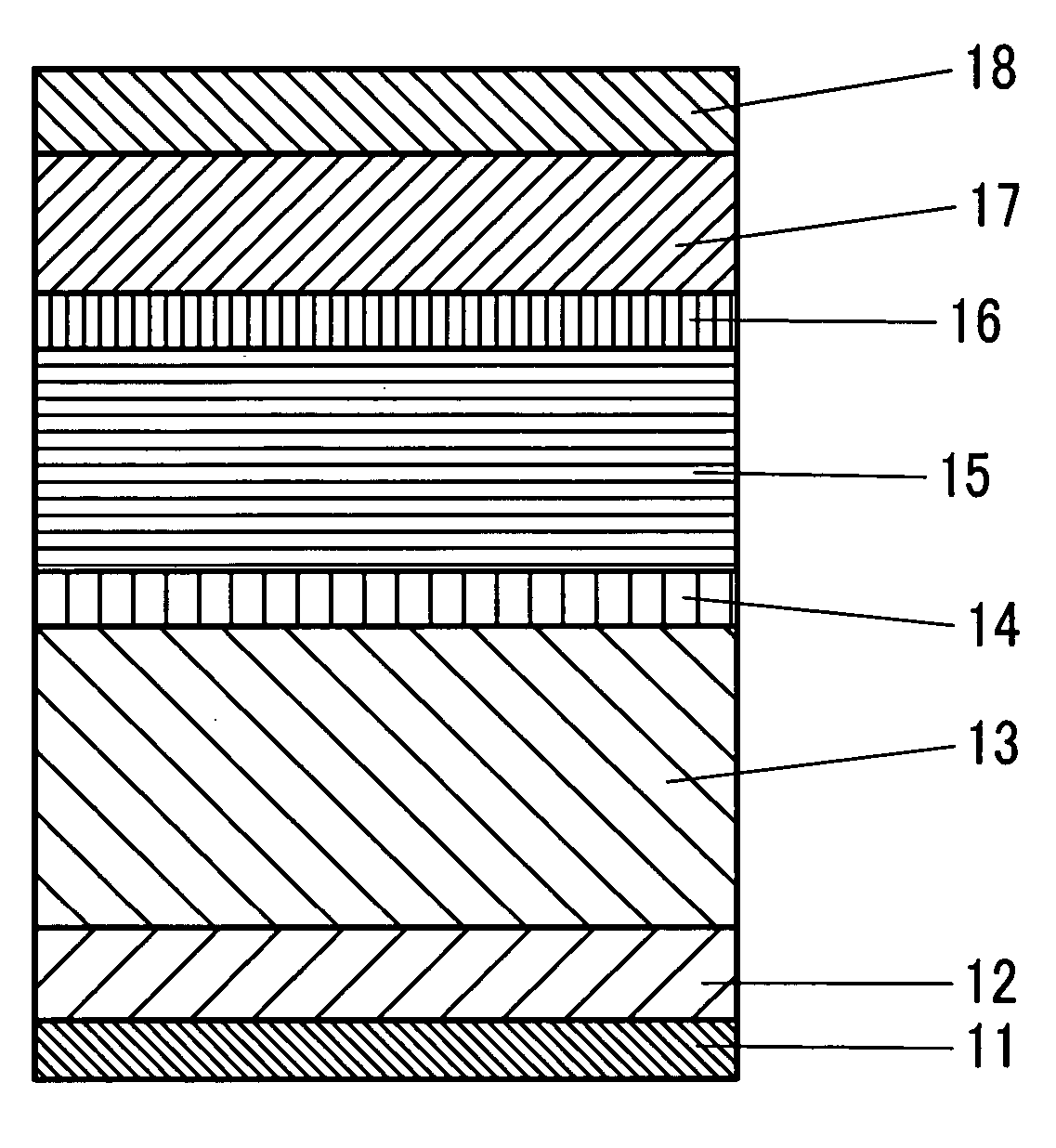
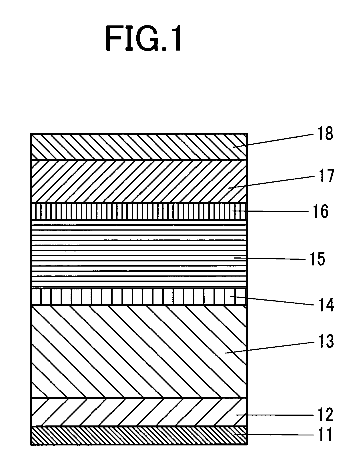
[0059]FIG. 1 describes a block diagram of a perpendicular magnetic recording medium in the example 1. On a substrate 11 are formed a pre-coat layer 12, a soft magnetic underlayer 13, a seed layer 14, a lower-intermediate layer 15, an upper-intermediate layer 16, a magnetic recording layer 17, and an overcoat layer 18 that are laminated sequentially on the substrate 11.

[0060] The substrate 11 is a crystallized glass substrate having a thickness of 0.635 mm and a diameter of 65 mm. At first, an Ni-37.5 at. % Ta-10 at. % Zr pre-coat layer 12 (NiTa37.5Zr10, hereinafter) is formed on the substrate to suppress the influence of chemical heterogeneity of the substrate surface and ununiformity of the temperature in the thermal treatment process on the soft magnetic underlayer. Then, a soft magnetic underlayer 13 is formed on the pre-coat layer 12. The soft magnetic underlayer 13 is made of FeTa8C12 having a total thickness of 200 nm.

[0061] The soft magnetic underlayer 13 is structured as a...

example 2

[0070] The perpendicular magnetic recording medium in this example 2 is manufactured in the same film structure and under the same deposition condition as those of the sample 1-7 in the example 1 except for the material of the upper-intermediate layer 16. In this example 2, the upper-intermediate layer 16 is made of a RuCo alloy in which the Ru content is changed from that in the example 1.

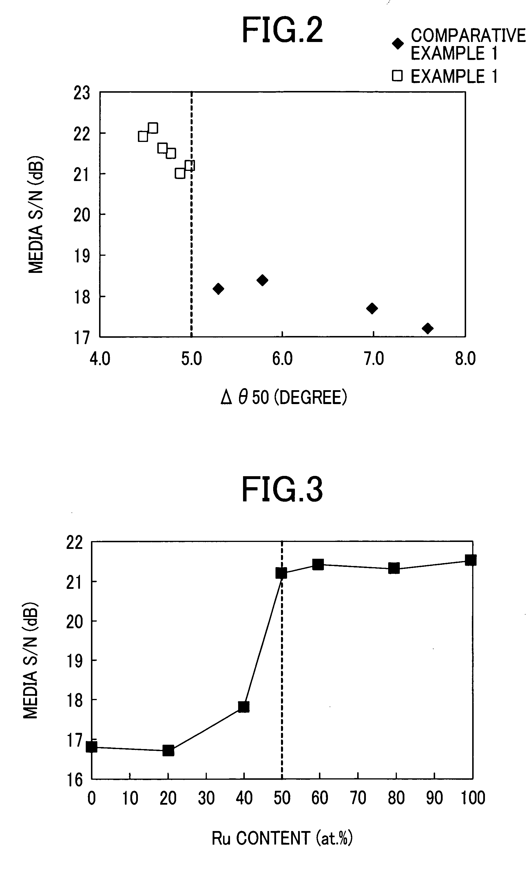
[0071]FIG. 3 illustrates a relationship between the Ru content and the media S / N value. As shown in FIG. 3, the media S / N value is lowered significantly when the Ru content is under 50 at. %. This admits that the more the Co content increases and the more the Ru content decreases, the less the lattice constant mismatch between the magnetic recording layer and the intermediate layer is reduced, thereby adjacent crystal grains come to be united more easily.

[0072] In other words, it is required to set the Ru content in the Ru-based alloy intermediate layer at 50 at. % and over and increase the latt...

example 3

[0078] The perpendicular magnetic recording medium in this example 3 is manufactured in the same film structure and under the same deposition condition as those of the sample 1-7 in the example 1 except for the upper-intermediate layer. In the sample in this example 3, a Ru alloy having a thickness of 5 nm is used to form the upper-intermediate layer. In the Ru alloy, a Si oxide is added to the upper-intermediate layer. The content of the Si oxide to be added in the upper-intermediate layer is changed to create a sample having a different mean crystal grain size in the magnetic recording layer.

[0079]FIG. 6 shows a result of composition analysis by X-ray photoelectron spectroscopy (XPS) with respect to the samples 3-11 and 3-14 in this example 3. The sample 3-14 is found to contain a Si oxide in the upper-intermediate layer.

[0080] As a sample to be compared with that in the example 3, the perpendicular magnetic recording medium is manufactured in the same film structure and under t...


PUM


Abstract

Disclosed here is a perpendicular magnetic recording medium for realizing a high media S / N value without degrading the magnetic isolation of crystal grains from each another. The perpendicular magnetic recording medium comprises a substrate, a soft magnetic underlayer formed on the substrate, an intermediate layer formed on the soft magnetic underlayer, and a magnetic recording layer formed on the intermediate layer. The intermediate layer consists of at least two or more layers and contains Ru or an Ru alloy and the magnetic recording layer is made of a material containing a CoCrPt alloy and oxygen. The crystallo graphic orientation of the recording layer can be improved enough without increasing the crystal grain size if a full width at half-maximum Δθ50 of the Rocking curves of the Ru (0002) diffraction peak measured by an X-ray diffraction method is 5° and under.

Description

CLAIM OF PRIORITY [0001] The present application claims priority from Japanese application JP 2003-320605 filed on Sep. 12, 2003, and Japanese application JP 2003-322433 filed on Sep. 16, 2003, the contents of which are hereby incorporated by reference into this application. FIELD OF THE INVENTION [0002] The present invention relates to a perpendicular magnetic recording medium and a method for manufacturing the same. BACKGROUND OF THE INVENTION [0003] The areal density of magnetic disk drives has increased by 100% every year since 1998. As the areal density increases, however, a so-called thermal decay problem has begun to arise remarkably. Consequently, it has been considered to be very difficult to go over an areal density of 15.5 gigabits per square centimeter. [0004] On the other hand, unlike the longitudinal recording method, the perpendicular recording method causes the demagnetizing field that works between adjacent bits to be reduced in proportion to an increase of the line...

Claims


Application Information

Patent Timeline
IPC IPC(8): G11B5/738G11B5/64G11B5/65G11B5/667G11B5/73G11B5/84G11B5/851
CPCG11B5/667G11B5/656G11B5/676G11B5/658
Inventor TAKEKUMA, IKUKONAKAGAWA, HIROYUKITAMAI, ICHIROHIRAYAMA, YOSHIYUKIHOSOE, YUZURU
Owner HITACHI LTD
Learn More