
Radiation image conversion panel and preparation method thereof

a technology of conversion panel and radiation image, which is applied in the direction of conversion screen, instruments, nuclear engineering, etc., can solve the problems of unstudied insufficient characteristics of luminance and sharpness relationship, and inability to achieve uniform distribution of crystal diameter, etc., to achieve deterioration of optical characteristics, high thermal expansion coefficient, and low shock resistance

Inactive Publication Date: 2005-03-24
KONICA MINOLTA MEDICAL & GRAPHICS INC
View PDF7 Cites 9 Cited by
  • Summary
  • Abstract
  • Description
  • Claims
  • Application Information

AI Technical Summary

Benefits of technology

Further in cases when forming a stimulable phosphor layer by depositing a stimulable phosphor by a process of gas phase deposition, a stimulable phosphor layer comprised of CsBr and the like exhibits a relatively high thermal expansion coefficient but results in a residual stress at the time of vapor deposition onto the support, producing problems such as warping of the stimulable phosphor layer. The thus warped phosphor layer affects the refraction index, deteriorating optical characteristics and resulting in image unevenness. In addition, warping often lowered shock resistance.
Accordingly, it is an object of this invention to provide a radiation image conversion panel with minimized warping and enhanced shock resistance as well as enhanced sensitivity.
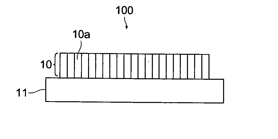
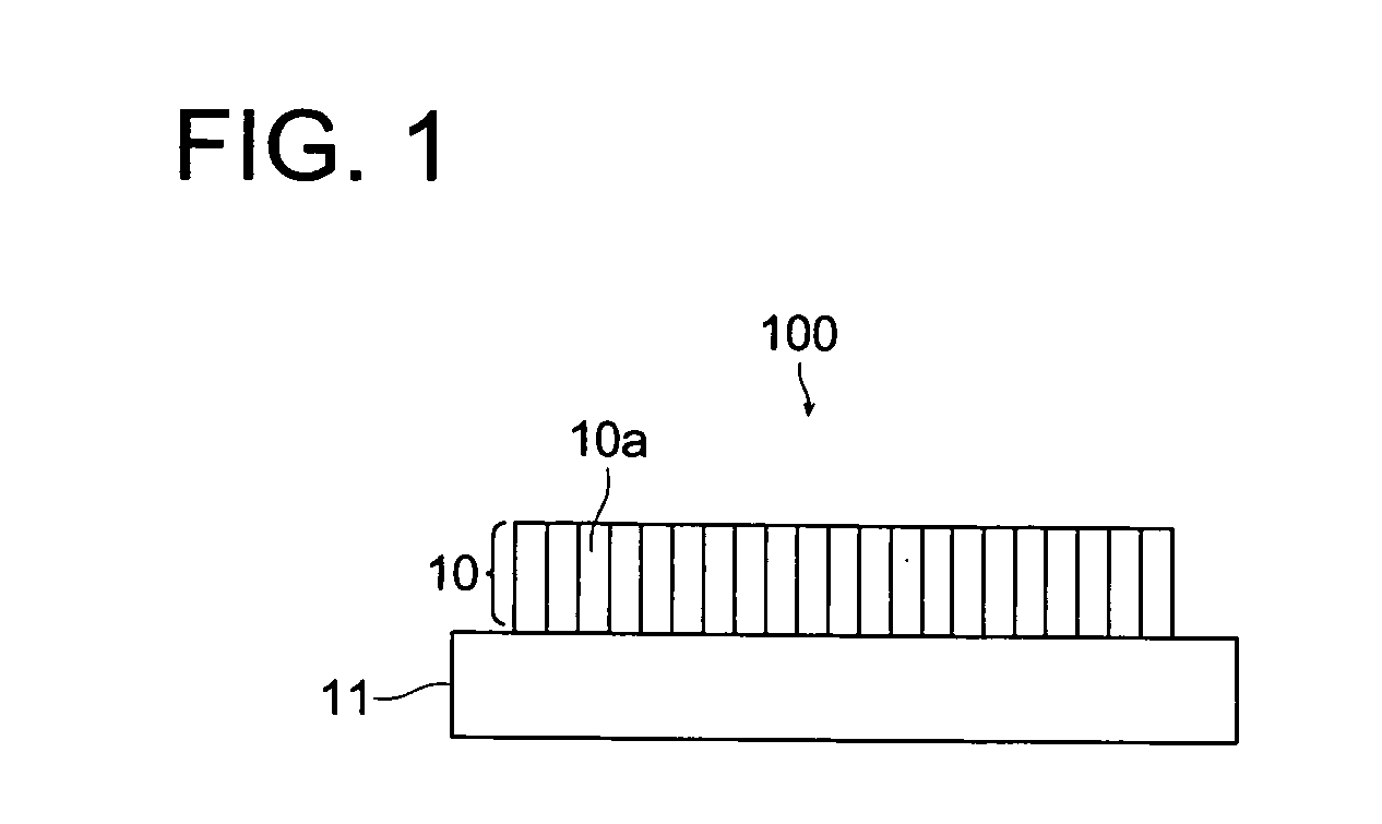
According to this invention, in a radiation image conversion panel having a phosphor layer comprising columnar crystals formed by the process of gas phase deposition, the distribution characteristic of crystal diameters becomes isotropic, whereby heat or stress is isotropically and evenly applied, resulting in reduced warping and enhanced shock resistance. Further, even distribution of crystal diameters within the phosphor layer can also minimize unevenness of sensitivity. Thereby, radiation images exhibiting superior image quality such as sharpness can be provided.

Problems solved by technology

However, even in radiation image conversion panels comprising a stimulable phosphor layer of columnar crystals formed by a gas phase growth process (deposition), the relationship of luminance and sharpness has not achieved sufficient characteristics and requires further improvement.
For example, in conventional radiation image conversion panels (such as disclosed in the foregoing patent document), although sufficient studies have been made with respect to the crystal form, the distribution of crystal diameters has not been studied and a non-uniform distribution of crystal diameters produced problems such as unevenness in sensitivity.
Further in cases when forming a stimulable phosphor layer by depositing a stimulable phosphor by a process of gas phase deposition, a stimulable phosphor layer comprised of CsBr and the like exhibits a relatively high thermal expansion coefficient but results in a residual stress at the time of vapor deposition onto the support, producing problems such as warping of the stimulable phosphor layer.
The thus warped phosphor layer affects the refraction index, deteriorating optical characteristics and resulting in image unevenness.
In addition, warping often lowered shock resistance.

Method used


Image

  • Radiation image conversion panel and preparation method thereof
  • Radiation image conversion panel and preparation method thereof
  • Radiation image conversion panel and preparation method thereof

Examples


example 1

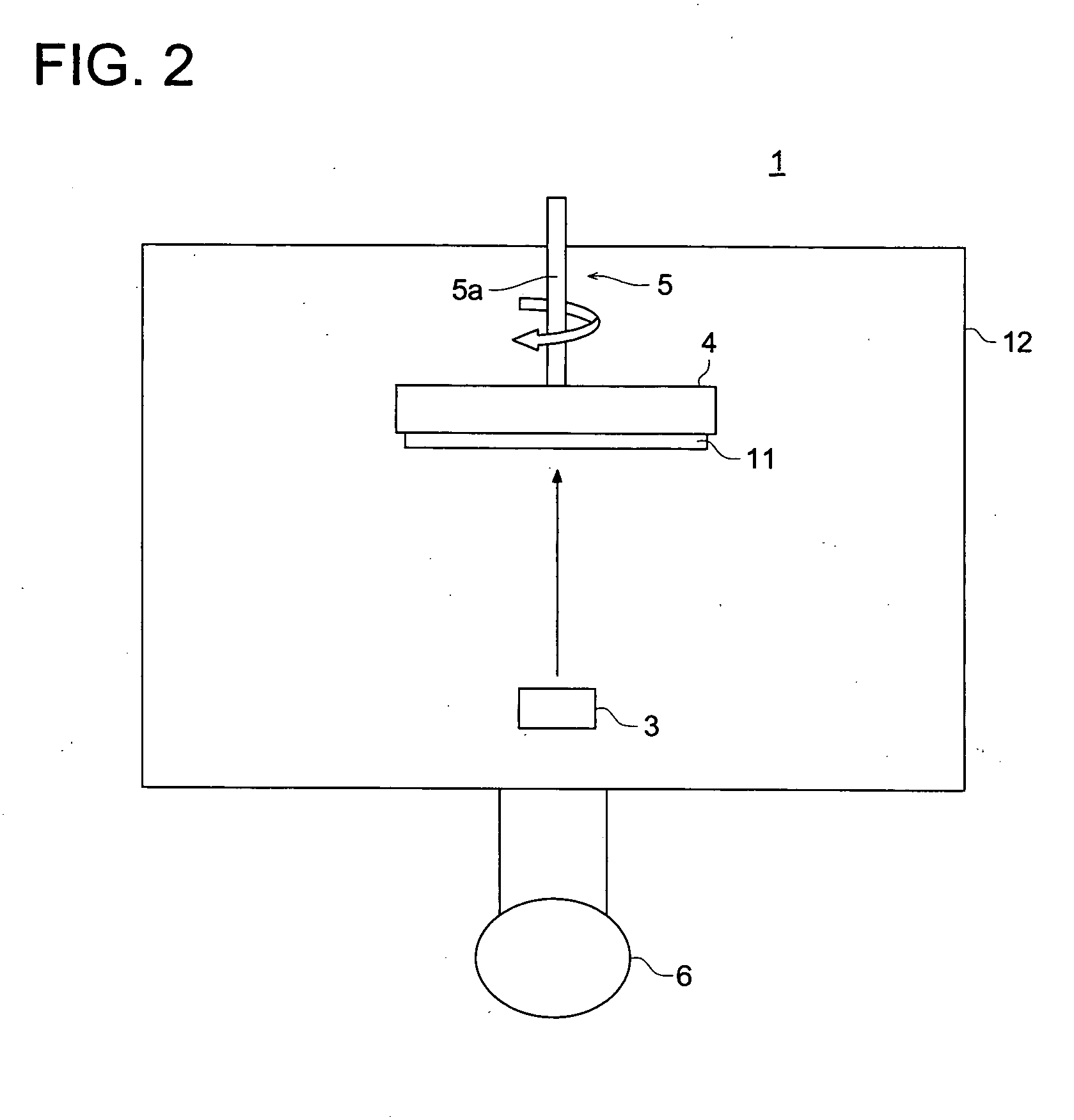
Using the vacuum deposition apparatus (1), raw material of the foregoing phosphor to be deposited was charged into a resistance heating crucible, and the support (11) was set to a rotatable support holder (4) and the distance between the support (11) and an evaporation source (3) was adjusted to 200 mm. Subsequently, the inside of the vacuum deposition apparatus (1) was evacuated and then, argon (Ar) gas was introduced thereto to adjust the degree of vacuum to 0.1 Ps; thereafter, the support (11) was maintained at a temperature of 100° C., while rotating the support (11) at a rate of 10 rpm. Subsequently, the resistance heating crucible was heated to deposit the stimulable phosphor and deposition was completed when the thickness of the stimulable phosphor layer reached 500 μm. Then, the thus formed stimulable phosphor layer was put into a protective layer package in dry air and sealed to obtain a radiation image conversion panel having a sealed stimulable phosphor layer.

example 2

Similarly to Example 1, deposition of a stimulable phosphor layer was carried out to obtain a radiation image conversion panel, except that the distance between the support (11) and the evaporation source (3) was adjusted to 300 mm.

example 3

Similarly to Example 1, deposition of a stimulable phosphor layer was carried out to obtain a radiation image conversion panel, except that the distance between the support (11) and the evaporation source (3) was adjusted to 400 mm.


PUM


Abstract

A radiation image conversion panel is disclosed, comprising a support having thereon a stimulable phosphor layer comprising columnar crystals of a stimulable phosphor, wherein the columnar crystals are isotropically distributed on the support outwardly from the center of the support with respect to columnar crystal diameter. There is also disclosed a preparation method thereof.

Description

FIELD OF THE INVENTION The present invention relates to a radiation image conversion panel comprising a stimulable phosphor layer and a preparation method thereof. BACKGROUND OF THE INVENTION Radiation images as represented by X-ray images are broadly employed for use in medical diagnosis. To obtain the radiation images, there has been practically used a radiation image recording and reproducing method using photo-stimulable phosphors (hereinafter, also denoted as stimulable phosphors) in which irradiated radiation energy is accumulated and recorded, and stimulated emission is caused upon exposure to stimulating light in proportion to the accumulated and recorded energy. A radiation image conversion panel used for the radiation image recording and reproducing method is basically comprised of a support provided thereon with a stimulable phosphor layer. Of stimulable phosphors is known one which is comprised of columnar form crystals formed by a process of gas phase growth (deposit...

Claims


Application Information

Patent Timeline
IPC IPC(8): C09K11/00C09K11/08C09K11/77C09K11/85G21K4/00
CPCG21K4/00C09K11/7733
Inventor KASAI, SHIGETAMINAKANO, KUNIAKISHIBUYA, HIDEKI
Owner KONICA MINOLTA MEDICAL & GRAPHICS INC
Learn More