

Encapsulated switching devices having heat emission elements
a switching device and heat emission element technology, applied in the field of electrical electricity generation and power distribution systems, can solve the problems of limiting the maximum rated current affecting the operation of the switching device, so as to improve the heat emission of passive cooling, impede direct heat emission to the environment, and increase the operating current
- Summary
- Abstract
- Description
- Claims
- Application Information
AI Technical Summary
Benefits of technology
Problems solved by technology
Method used
Image

Examples
Embodiment Construction
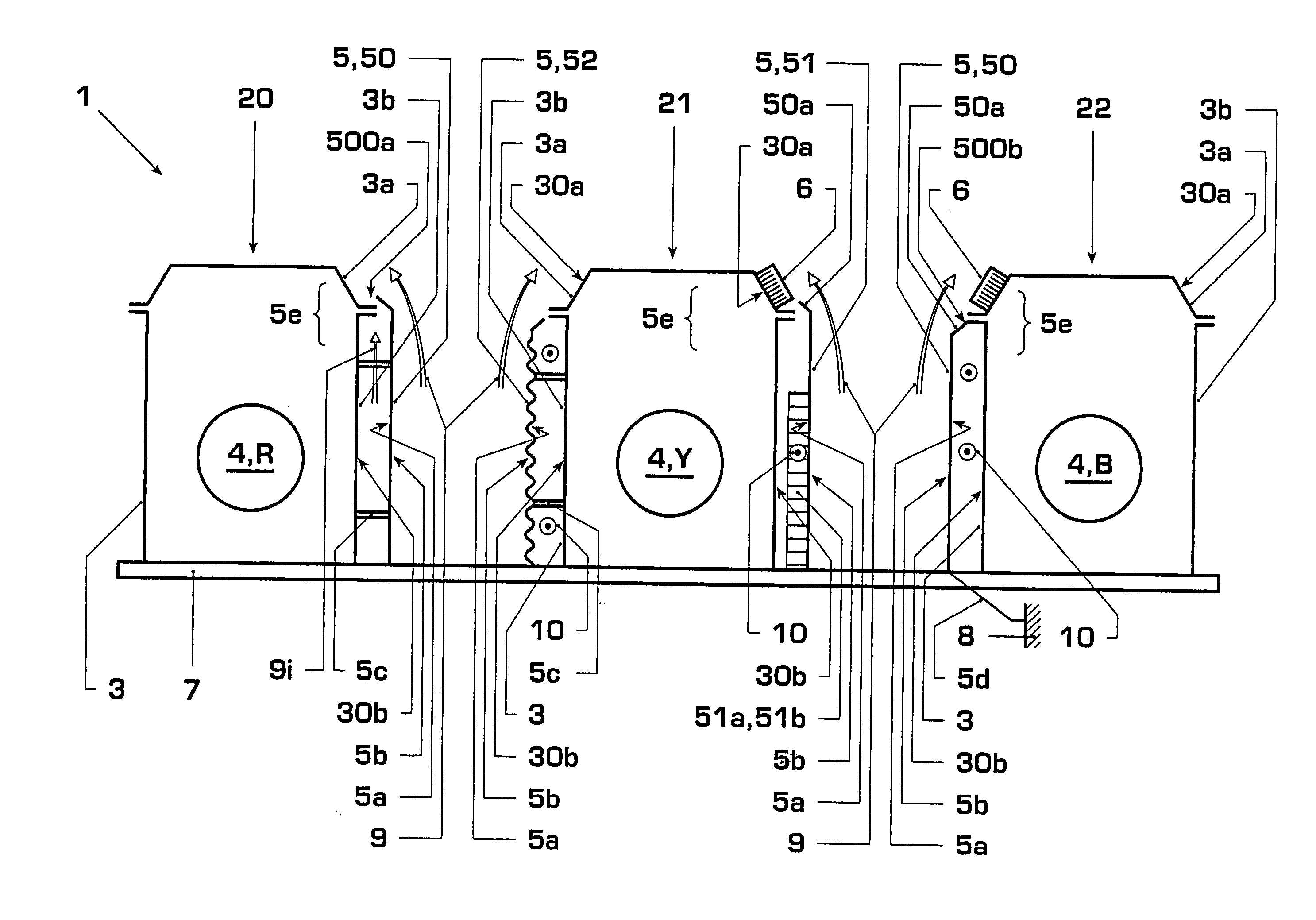
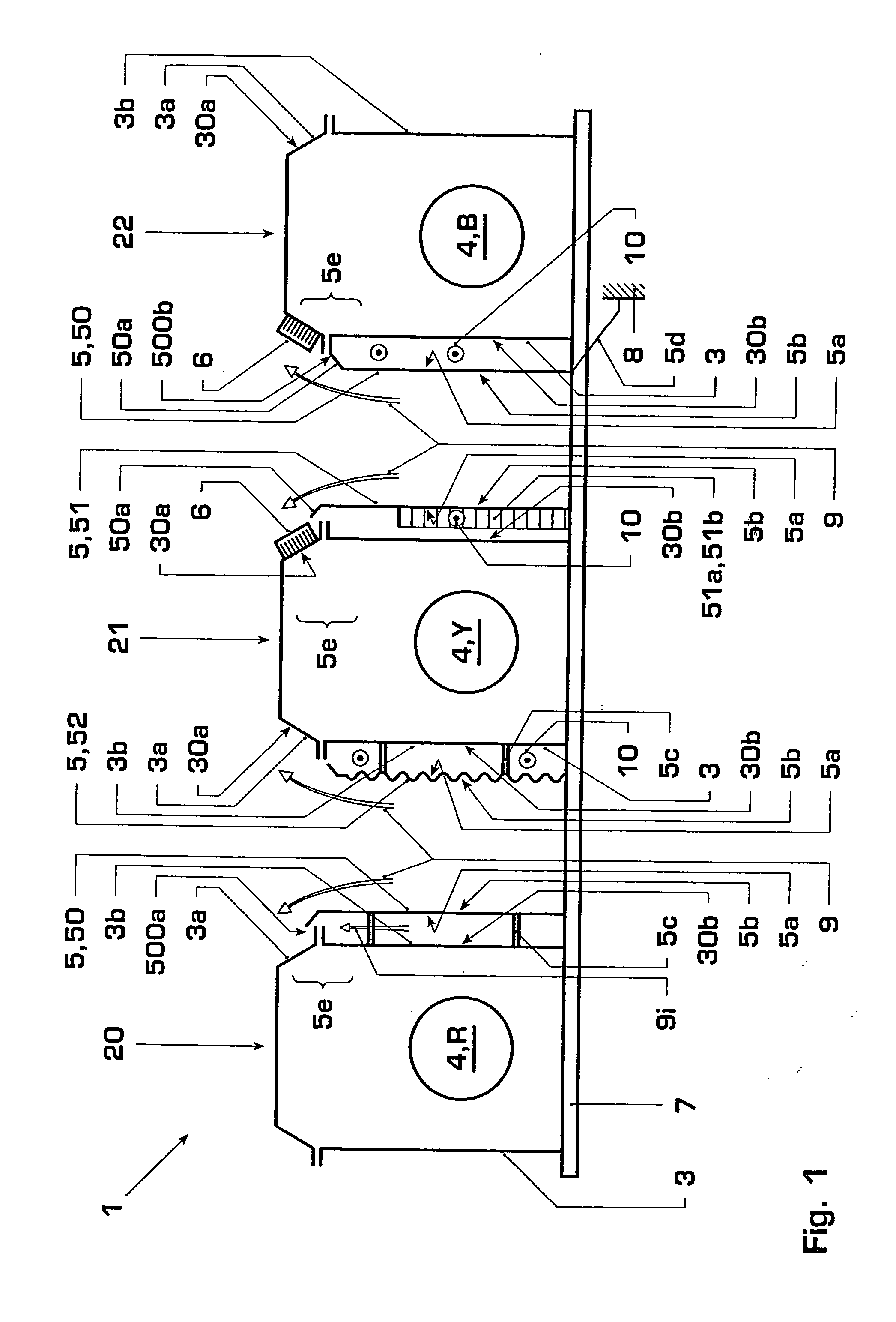
[0006] The object of the present invention is to specify electrical equipment items for carrying and / or switching heavy currents and / or high voltages and an electrical high-voltage system with such equipment items, which are distinguished by an improved rating and / or a more compact configuration. According to the invention, this object is achieved by the features of the independent claims.
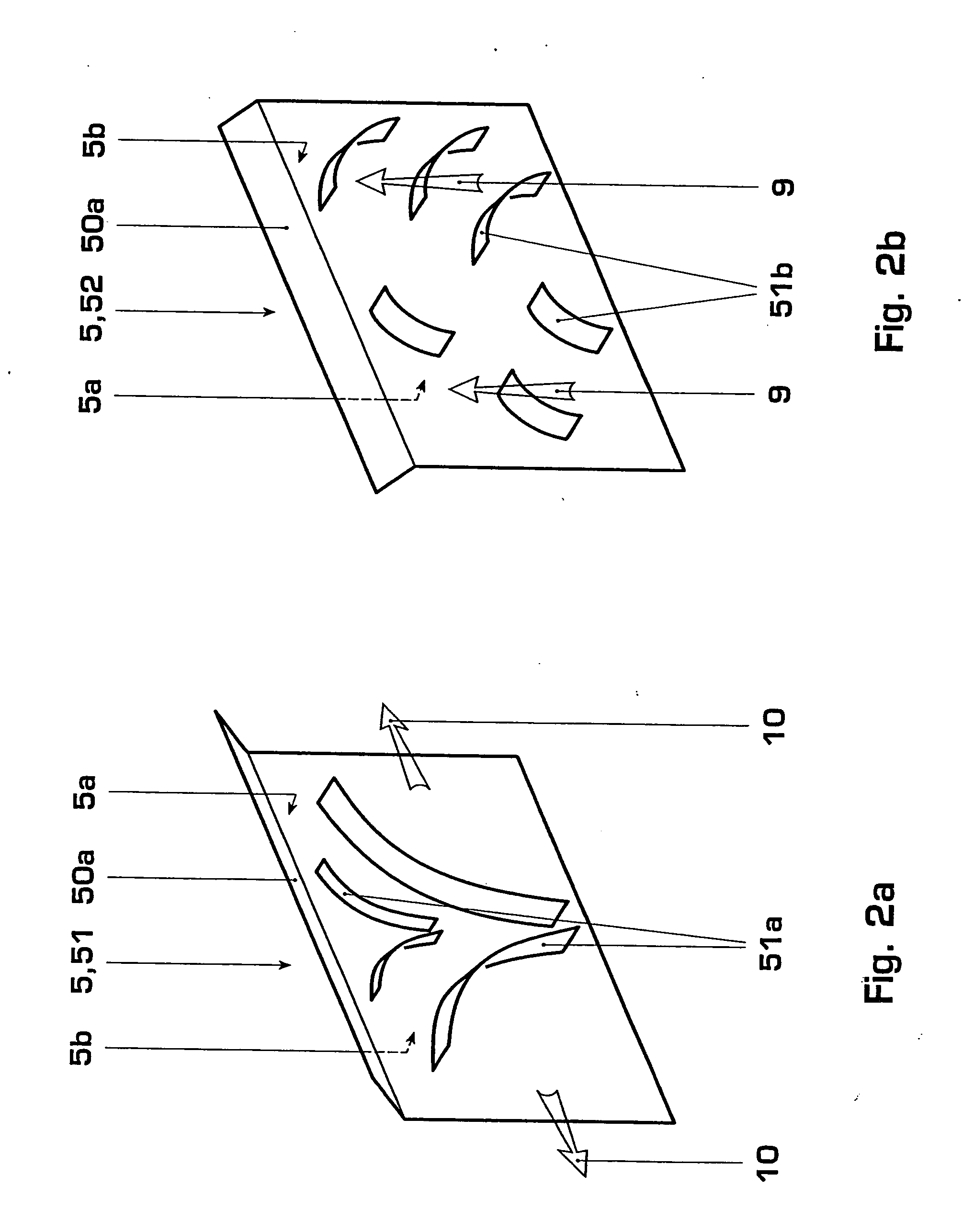
[0007] In a first aspect, the invention comprises a section of an electrical high-voltage system for carrying and / or switching heavy currents and / or high voltages, comprising electrical equipment items for at least three phases, with the equipment items being arranged in encapsulation and being covered by encapsulation covers, and adjacent encapsulations exchanging heat with one another via in each case at least one encapsulation side wall, with at least two intermediate plates furthermore being arranged between two encapsulation side walls and being used for heat absorption from at least one enca...
PUM
 Abstract
Description
Claims
Application Information