Automatic detection and window virtualization for flow control

a flow control and automatic detection technology, applied in the field of computer network processing, networking equipment, networking protocols, can solve the problems of limiting the maximum tcp performance according to the model, ip is a connectionless, best-effort, unreliable, etc., to increase the system functionality, increase the window size, and increase the data buffering capability

Active Publication Date: 2005-03-24
CITRIX SYST INC
View PDF99 Cites 66 Cited by
  • Summary
  • Abstract
  • Description
  • Claims
  • Application Information

AI Technical Summary

Benefits of technology

At this point the process has now identified both the first flow control module and the second flow control module in the data path. With this information the process may be structured to configure communications involving flow control modules to increase system functionality, such as window virtualization. Window (or buffer) virtualization allows increasing data buffering capabilities within a session despite having end nodes with small buffer sizes, e.g., typically 16 k bytes. Moreover, increases window size allows increasing buffer capacity at points within a data path. In turn, this allows for increased data throughput for the session because data can be transmitted quickly between end nodes and flow control modules and in large volume between flow control modules. Further, this can be done without interfering with the end nodes, which may continue to operate with small buffer sizes.

Problems solved by technology

IP is a connectionless, best-effort, unreliable, routable networking protocol.
Other phenomena may limit performance below what the model provides as a maximum.
For example, if the receiver does not advertise a window that is at least as large as the bandwidth delay product of the connection, then maximum TCP performance will be limited accordingly.
Standard implementations of TCP are also known to perform poorly in certain environments and / or conditions.
For example, the high rate of packet loss in typical wireless links results in poor TCP performance.
However, this is frequently not a viable option such as when the source code is unavailable or when there are too many endpoints to manage conveniently.
This technique suffers from at least two disadvantages: first, the extra expense of the additional processing node and its associated administrative overhead; and second, the conventional PEP often requires redundant processing due to the poor integration with the other nodes of the network.
Even with access to the source code of an operating system, the operational issues associated with supplying and supporting customized versions of the operating system make this prohibitive in many environments.
Requiring large amounts of these resources not only increases system expense, but also requires additional environment attention (more power, more space, etc.) and also reduces overall system reliability.
Some prior art techniques translate the TCP / IP protocol into other protocols (e.g., User Datagram Protocol (UDP)), causing disruption to network monitoring, traffic shaping, Quality of Service (QoS), Service Level Agreement (SLA), statistics measuring applications, and others; they also require modifications to firewall and security settings due to the usage of protocols that were not previously employed.
Across all of these dimensions, no algorithm can be optimal.
The transcoding from FTP to UDP interferes with any network element that might attempt to process the individual TCP connection, such as QoS, SLA or traffic management.
However, general-purpose lossless data compression is typically limited to a two- to three-times reduction in data, placing an upper limit on the total performance improvement that can be provided by this technique.
Further, many data types are already compressed, wasting system resources attempting any further compression for these data types.
The computational expense of this method requires the addition of an extra box to the network and limits the speed at which packets can be processed.
The product does not address the fundamental limits of the TCP / IP protocol and is thereby permanently limited to a maximum of two- to three-times performance improvement over offerings without the PEP.

Method used


Image

  • Automatic detection and window virtualization for flow control
  • Automatic detection and window virtualization for flow control
  • Automatic detection and window virtualization for flow control

Examples


Embodiment Construction

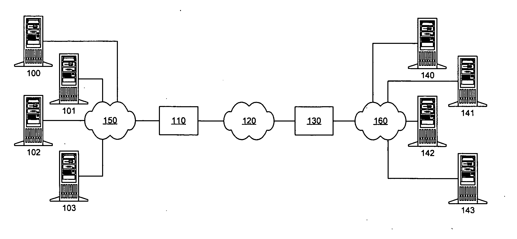
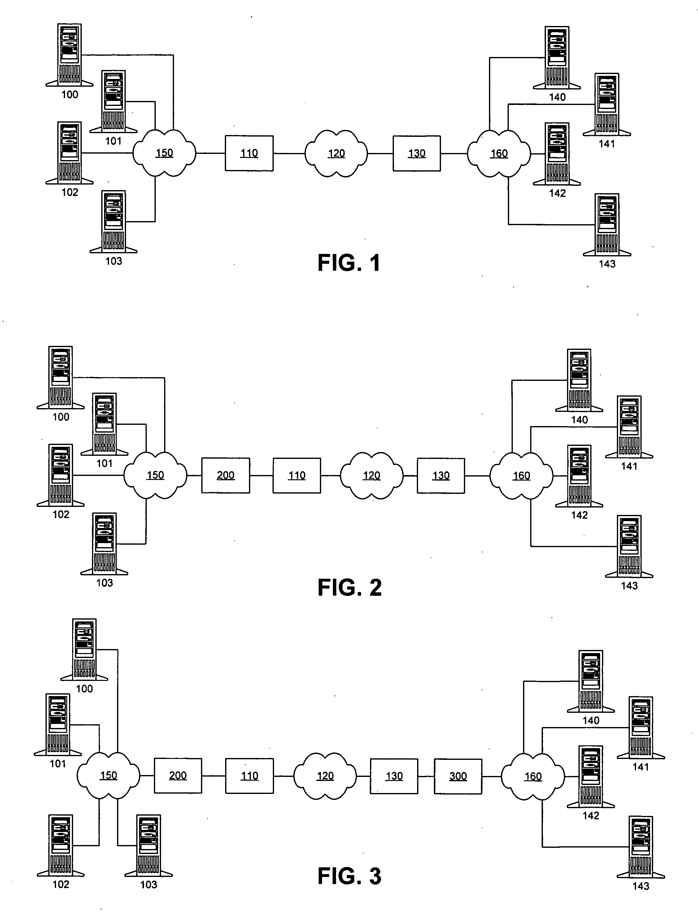
The present invention addresses the deficiencies of conventional PEPs. Several advances in the state of the art are provided, eliminating numerous barriers to deployment present in the prior art solutions. The present invention can be deployed into a network without requiring significant additional resources. The present invention is not fundamentally limited in its performance boost by RTT. Minimal additional latency is introduced by its presence in the network, allowing the PEP benefits to be extended to connections with small RTTs. Distributed implementations of the present invention support redundantly connected networks in order to provide superior reliability and scalable performance.

No changes in the network topology are required to obtain the benefits of the invention. No changes in application or utility programs or operational procedures are required. The invention interoperates seamlessly with the existing security, performance, QoS, SLA, traffic, and network managemen...


PUM


Abstract

One or more flow control modules, implemented on various types of network topologies, provide a number of functionalities for controlling the flow of IP packets (such as TCP / IP packets) over a network connection. The flow control modules may be implemented within a sender and / or receiver or may be deployed into a network as a separate device without requiring significant additional resources.

Description

BACKGROUND 1. Field of the Invention This invention pertains to the processing of computer networks, networking equipment, and networking protocols, and in particular to systems that enhance the performance of existing networking applications through the deployment of additional networking entities. 2. Background of the Invention Many computer networking technologies and protocols are well known. One of the most widely used protocols is the Internet protocol (IP). IP is a connectionless, best-effort, unreliable, routable networking protocol. Applications that require reliable communications typically use the Transmission Control Protocol (TCP) on top of IP. The TCP protocol layer provides required functionality such as flow control, packet loss detection, lost packet retransmission, congestion avoidance, etc. (hereinafter referred to as upper-layer behaviors) that are needed to provide reliable communications over the unreliable IP networking substrate. This pair of networking p...

Claims


Application Information

Patent Timeline
Patent Type & Authority Applications(United States)
IPC IPC(8): H04L12/26H04L12/28H04L12/56
CPCH04L12/24H04L41/00H04L41/12H04L67/2876H04L69/166H04L67/28H04L69/16H04L67/56
Inventor SAMUELS, ALLEN R.SUTTER, PAUL G.
Owner CITRIX SYST INC
Why Eureka
Try Eureka