Internal PEM fuel cell water management

a fuel cell and pem technology, applied in the field of internal pem fuel cell water management, can solve the problems of large capillary pressure, achieve the effects of reducing parasitic power, improving pem fuel cell stacks, and reducing parasitic power

Inactive Publication Date: 2005-03-24
INT FUEL CELLS
View PDF3 Cites 32 Cited by
  • Summary
  • Abstract
  • Description
  • Claims
  • Application Information

AI Technical Summary

Benefits of technology

[0009] Objects of the invention include: PEM fuel cells which do not require a mechanical water pump, a water accumulator or any other water management apparatus external to the fuel cell stack; PEM fuel cells of greater efficiency; PEM fuel

Problems solved by technology

This mechanism results in a larger capillary pressure within the anode water transport plates relative to the cathode

Method used


Image

  • Internal PEM fuel cell water management
  • Internal PEM fuel cell water management
  • Internal PEM fuel cell water management

Examples


Embodiment Construction

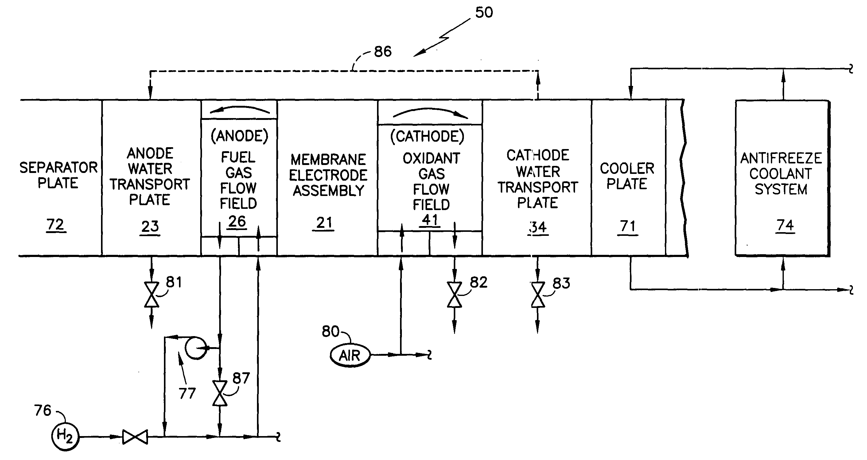
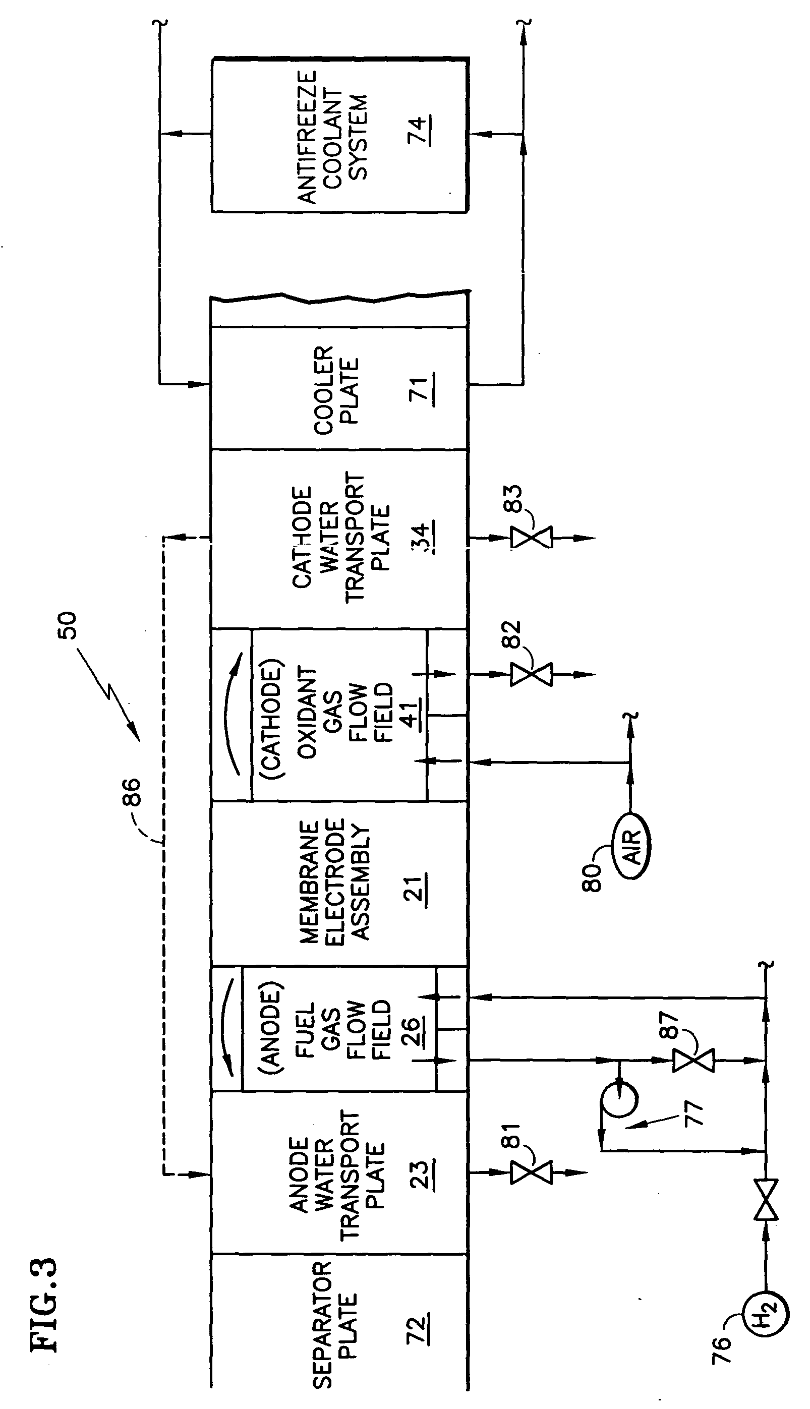
[0026] Referring to FIG. 3, the concept of the present invention is illustrated schematically, in a fuel cell stack 50 having cooler plates 71 separating the fuel cells into groups of 2-4 fuel cells per group, and with separator plates 72 separating fuel cells which are not themselves separated by the cooler plates. Antifreeze coolant is provided by an antifreeze coolant system 74 to all of the cooler plates 71 of the stack 50.

[0027] A fuel such as hydrogen is provided to the anode fuel gas flow field from a source 76 and may include a fuel recycle loop 77. An oxidant, such as oxygen or air 80, may be provided to the cathode oxidant gas flow field 41. Valves 81, 83 may be provided so as to drain water from the water transport plates 23, 34. Valves 82, 87 may be provided to control the reactant pressures in the fuel gas flow field 26 and the oxidant gas flow field 41.

[0028] The concept of the invention is providing water transfer capability 86 for water to flow internally of the fu...


PUM


Abstract

Water transfer means (86) transfers fuel cell product water from a cathode water transport plate (34) to an anode water transport plate (23) of the same or a different fuel cell, wholly within a fuel cell stack (50), (disposed within each fuel cell of a fuel cell stack (50)). The water transfer means may be a very high permeability proton exchange membrane (21a), a water transfer band (90) such as silicon carbide particles, a porous water transfer zone (107), with or without a flow restrictor (109), internal water manifolds (112, 113) which extend through an entire fuel cell stack, or internal manifolds (112a, 112b, 112c, 112d, 113a, 113b, 113c, 113d) which extend only through groups of cells between solid plates (71). As an example, 90% product water may be removed as vapor in oxidant exhaust, 30% may be transferred through the water transfer means (86) from cathode water transport plates to anode water transport plates, of which 20% may flow from the anode to the cathode, the net result of osmosis and proton drag, and 10% may exit the anode water transport plates as liquid water.

Description

TECHNICAL FIELD [0001] This invention relates to transferring water from the cathodes of PEM fuel cells to the anodes of PEM fuel cells, without external flow paths external to the fuel cell stack, either within a single cell or a small group of cells, without comingling water from other cells, or throughout an entire fuel cell stack. BACKGROUND ART [0002] In FIG. 1, a conventional fuel cell stack 14 has about 300 fuel cells; only a fuel cell 16 and portions of adjacent fuel cells 18, 19 are shown. The fuel cell 16 comprises a membrane electrode assembly (MEA) 21 which includes a proton exchange membrane together with cathode and anode catalysts. An anode support plate 22 is adjacent to a porous anode water transport plate 23, which includes fuel flow field passages 26 and grooves 28 which make up coolant water passageways 29 when matched with grooves 30 on an adjacent cathode water transport plate 31. Similarly, a cathode support plate 32 is adjacent to a porous cathode water trans...

Claims


Application Information

Patent Timeline
IPC IPC(8): H01M8/02H01M8/04
CPCH01M8/0234H01M8/0267H01M8/04029H01M8/04097H01M8/04119H01M8/04141Y02T90/32H01M8/04156H01M8/04171H01M8/04291H01M2250/20Y02E60/50H01M8/04149H01M8/0258H01M8/241H01M8/2483Y02T90/40
Inventor BREAULT, RICHARD D.HARRINGTON, MICHAEL D.SRIBNIK, FREDERICK
Owner INT FUEL CELLS
Why Eureka
Try Eureka