Catalytic combustors

a technology of catalytic combustors and combustion gas turbines, which is applied in the direction of combustion types, physical/chemical process catalysts, and combustion using catalytic materials, can solve the problems of reducing affecting the efficiency of operation, so as to improve the effect of subsequent chemical bonding

Inactive Publication Date: 2005-03-31
SIEMENS ENERGY INC
View PDF17 Cites 12 Cited by
  • Summary
  • Abstract
  • Description
  • Claims
  • Application Information

AI Technical Summary

Benefits of technology

[0011] Preferably, the coating applied to the exterior of the duct is a less dense, porous, compositionally similar structure, within which the catalyst material is contained. The density of the non-catalytic coating applied, for example, to the inner surface of the tubes can be up to approximately between 10% to 50% denser and, preferably, 25% denser than the catalytic coating. The bi-functionality of the external coating serves as the catalytic matrix, as well as a temperature, corrosion and/or oxidation resistant coating, protecting the underlying metal substrate. In contrast, the d

Problems solved by technology

The combustion of such lean mixtures can, however, be somewhat unstable and thus catalytic combustion principles have been applied to such lean combustion systems to stabilize the combustion process.
The requirement to preheat the fuel/air mixture to improve the stability of the catalytic process reduces the efficiency of the operation.
When exposed to typical process temperatures within the combustor section, the ceramic wash coat can be subjected to spalling and/or

Method used


Image

  • Catalytic combustors
  • Catalytic combustors
  • Catalytic combustors

Examples


Embodiment Construction

[0019] The preferred embodiment of this invention is a catalyst supporting structure for a catalytic combustor. The catalyst supporting structure provides for improved bonding of the catalyst-containing coating with the underlying metal substrate, and renders the metal support structure resistant to oxidation that would otherwise degradate the support capability of the structure over time.

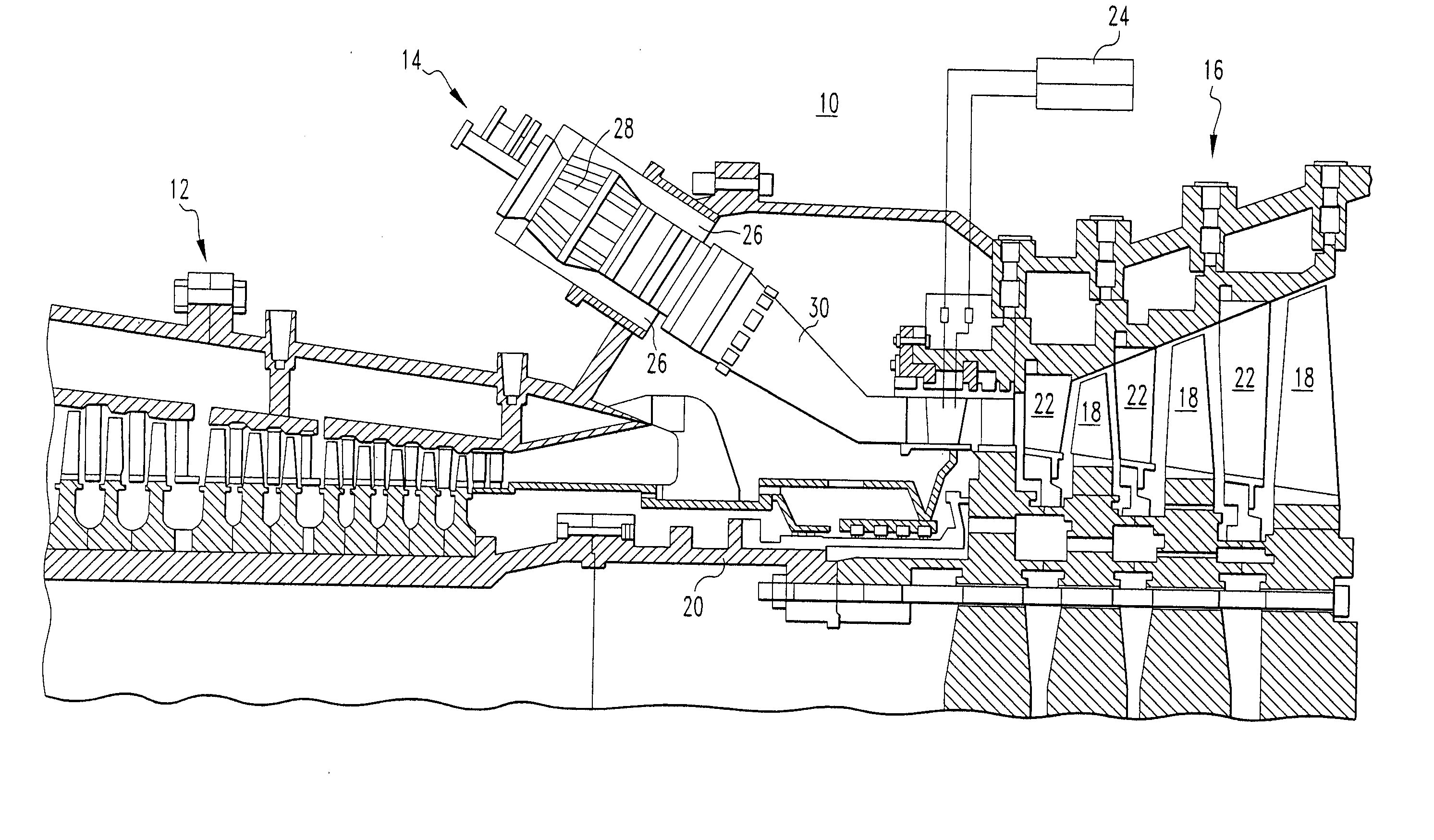
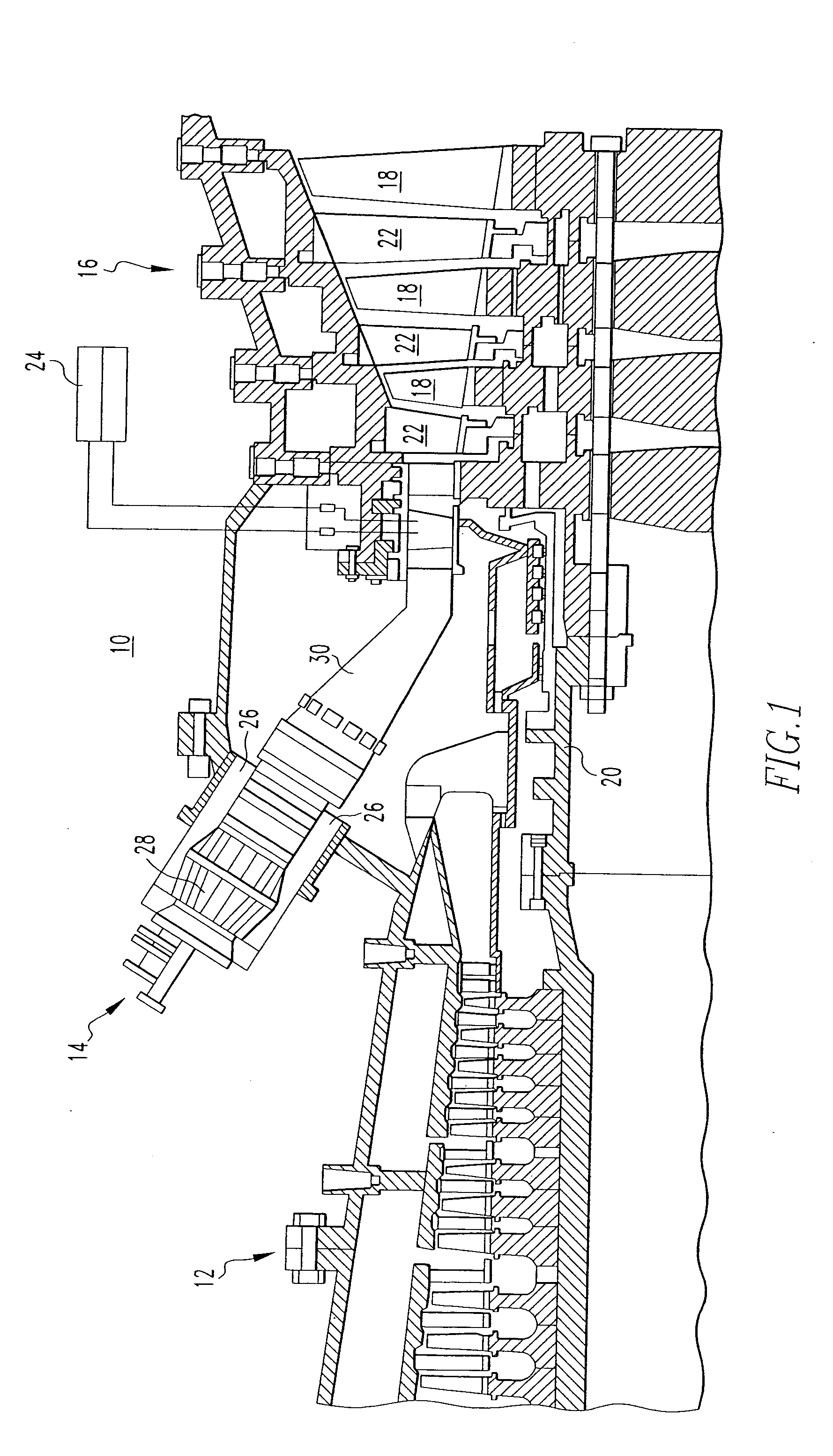
[0020]FIG. 1 illustrates a combustion turbine 10. The combustion turbine 10 includes a compressor section 12, at least one combustor 14, and a turbine section 16. The turbine section 16 includes a plurality of rotating blades 18, secured to a rotatable central shaft 20. A plurality of stationery vanes 22 are positioned between the blades 18, with the vanes 22 being dimensioned and configured to guide a working gas over the blades 18.

[0021] In use, air is drawn in through the compressor 12, where it is compressed and driven towards the combustor 14, with the air entering through air intake 26. Fro...


PUM

PropertyMeasurementUnit
Fractionaaaaaaaaaa
Fractionaaaaaaaaaa
Fractionaaaaaaaaaa

Abstract

A catalytic combustor for a combustion turbine that employs a protective nickel aluminide diffusion barrier on its inside and outside surfaces with a porous alumina, zirconia, titania, and/or ceria, and bond phase coating on the outside surface in which a catalyst is contained.

Description

BACKGROUND OF THE INVENTION [0001] 1. Field of the Invention [0002] The present invention relates generally to combustion gas turbine engines and, more particularly, to combustion gas turbine engines that employ catalytic combustion principles in the environment of a lean premix burner. [0003] 2. Related Art [0004] As is known in the relevant art, combustion gas turbine engines typically include a compressor section, a combustor section and a turbine section. Large quantities of air or other gases are compressed in the compressor section and are delivered to the combustor section. The pressurized air in the combustor section is then mixed with fuel and combusted. The combustion gases flow out of the combustor section and into the turbine section where the combustion gases power a turbine and thereafter exit the engine. Commonly, the turbine section includes a shaft that drives the compressor section, and the energy of the combustion gases is greater than that required to run the com...

Claims


Application Information

Patent Timeline
IPC IPC(8): B01J21/04F23C13/00F23R3/40
CPCF23C13/00F23R3/40F23C13/08
Inventor ALVIN, MARY ANNEMUCHA, BASILKLOTZ, JAMES
Owner SIEMENS ENERGY INC
Why Eureka
Try Eureka