Electrolytic method in diaphragm-type cell

a diaphragm-type cell, electrolysis technology, applied in the direction of electrolysis components, instruments, optics, etc., can solve the problems of difficult to exist in the form of dissolved cl, difficult to obtain soluble cl, difficult to leach precious metals, etc., to achieve enhanced leaching efficiency of hard-to-leach precious metals, low reaction efficiency, and high reaction efficiency

Inactive Publication Date: 2005-03-31
JX NIPPON MINING& METALS CORP +1
View PDF5 Cites 16 Cited by
  • Summary
  • Abstract
  • Description
  • Claims
  • Application Information

AI Technical Summary

Benefits of technology

[0031] (1) The anolyte reaction-efficiency is especially high. The oxidation-reduction potential (ORP) is as low as less than 500 mV in the conventional leaching cell. It is possible according to the present invention to maintain oxidation-reduction potential (ORP) exceeding 700 mV in the leaching cell. Leaching efficiency of the hard-to-leach precious metals is therefore enhanced.
[0032] (2) In the conventional method, the concentration of NaBr was 28 g / L because of low reaction efficiency. In the present invention, the reactions can be maintained at 24 g / L of NaBr. Accordingly, the feeding amount of NaBr, which is expensive, can be reduced, and, the removal of Ag+ by the cementation is increased by 2 mg / L. The silver can, therefore, be recovered more effectively than by method of the prior art.

Problems solved by technology

It turned out that the electric power loss and the loss of chlorine component are incurred in the method of the U.S. patent.
Since the oxidation reaction in the anode compartment does not effectively proceed, the formation of the soluble Br2 and BrCl2− are not satisfactory.
The Cl2 gas is difficult to exist in the form of dissolved Cl in the liquor.
The liquor, from which the Cl2 gas generates, is difficult to use for leaching.
In addition, since the formation of Cl2 gas is result of non-formation of BrCl2−, the Cl2 gas not only impedes the leaching but also incurs the chlorine loss.
This leads to increasing the load of the Ag recovery step and increases the cost.

Method used


Image

  • Electrolytic method in diaphragm-type cell
  • Electrolytic method in diaphragm-type cell
  • Electrolytic method in diaphragm-type cell

Examples


example 1

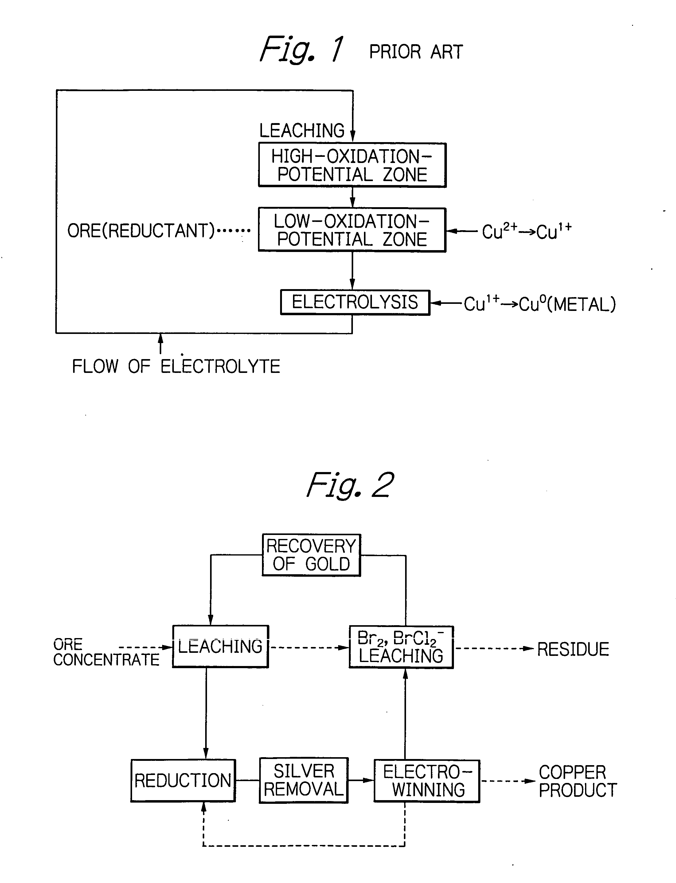
[0041] The leaching of the chalcopyrite and electrolytic winning of copper were carried out by the flow as shown in FIG. 2. Leaching of Cu2+ and the Br2 and BrCl2− leaching shown in the flow chart of FIG. 1 were carried out under the conditions of Example 1 of the U.S. patent. Recovery of Au was carried out following Example 3 of the U.S. patent.

[0042] In the flow chart of FIG. 2, the solid line indicates the flow of liquor, while the dotted line indicates the flow of solid. The copper product of the electro-winning step is partially returned to the reduction step, where Cu2+ is reduced to Cu1+ by using the copper product. The returned Cu1+ causes the cementation of Ag. The Ag concentration was decreased to slightly less than 20 mg / L in the reducing step.

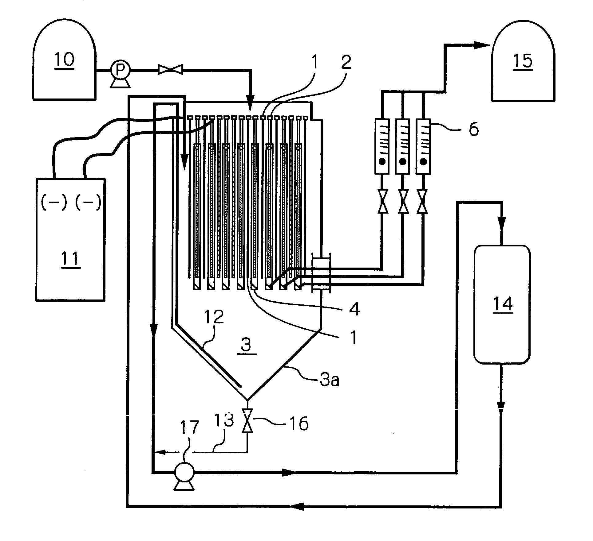
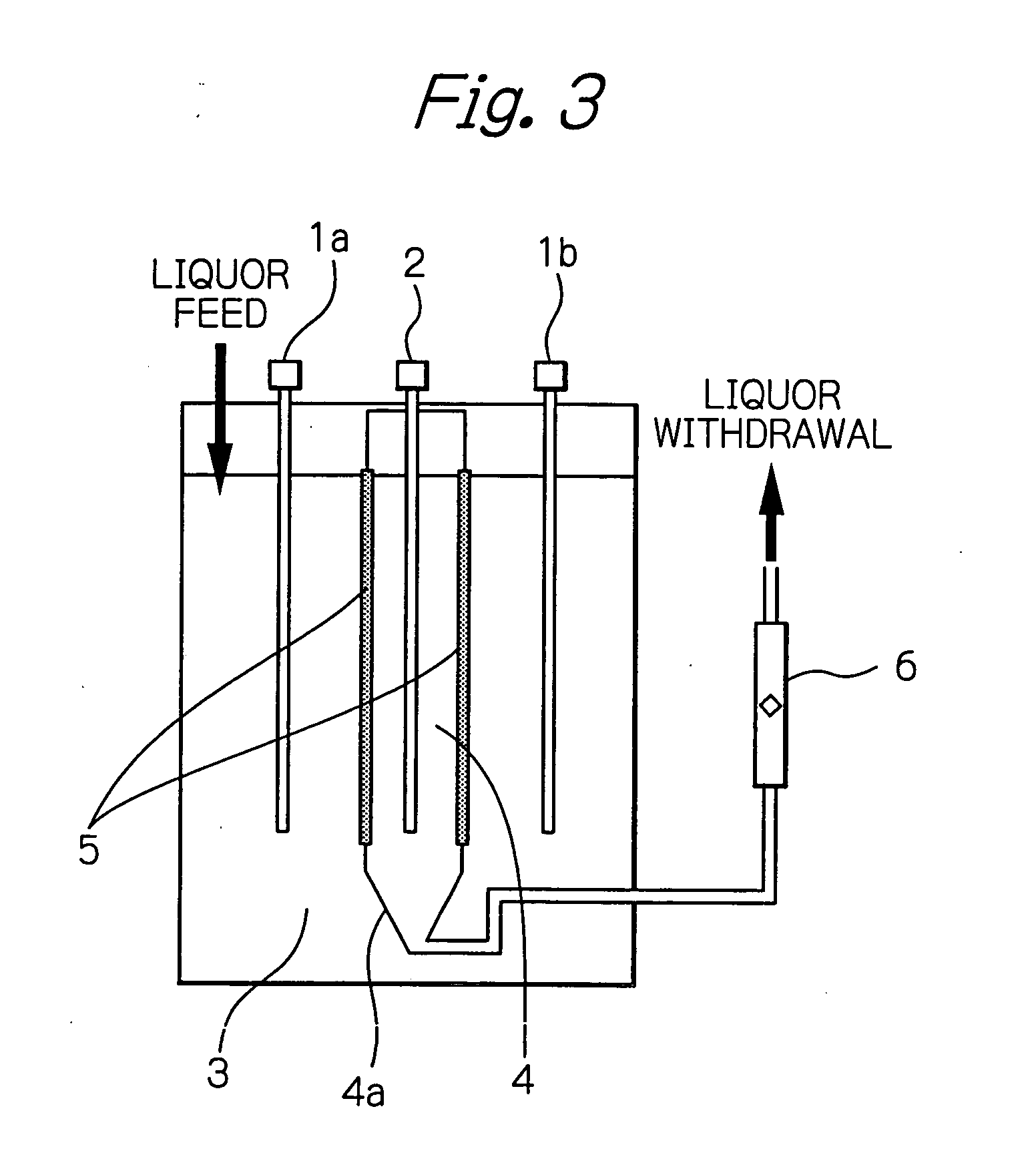
[0043] The electrolysis was carried out using an electrolytic cell shown in FIGS. 3 and 4. The eight anodes 2 used were DSA (dimension stable anode) 1300×250×3 mm in size. The nine cathodes 1 used were Ti plate of the same size as...


PUM

PropertyMeasurementUnit
oxidation-reduction potentialaaaaaaaaaa
concentrationaaaaaaaaaa

Abstract

In a metal-winning method, copper ore or copper-ore concentrates is effectively hydraulically leached in a chloride leach liquor and the resultant leached liquor is diaphragm-electrolyzed. A chloride electrolyte containing Brions and the leached metals is subjected to a diaphragm-electrolysis in an electrolytic cell comprising an anode compartment (4) and a cathode compartment (3). A portion of the electrolyte in the anode compartment (4) is withdrawn from below an anode (2) of the anode compartment (4) and is returned to the leaching step so as to increase the oxidation potential of the chloride leach liquor.

Description

BACKGROUND OF INVENTION [0001] 1. Field of Invention [0002] The present invention relates to a hydro-metallurgical process for producing metals by means of leaching a mineral, particularly a production process of base and precious metals from copper ore or copper-ore concentrates. More particularly, the present invention relates to a metal-winning method for effectively hydraulically leaching the copper ore or copper-ore concentrates, followed by electrolysis of the leached liquor using a diaphragm-type cell. [0003] 2. Description of Related Art [0004] Most copper ores which are subjected to smelting are sulfide ores. Among them, chalcopyrite is the most frequently smelted. Meanwhile, the sulfide minerals may also be subjected to a hydrometallurgical process, which is roughly classified into an atmospheric pressure leaching method and a pressurized leaching method. Known atmospheric pressure leaching methods are an acid-leaching method and a halide-leaching method. The halide leachi...

Claims


Application Information

Patent Timeline
Patent Type & Authority Applications(United States)
IPC IPC(8): C22B3/04C22B15/00C25C1/12C25C7/00C25C7/06
CPCC22B11/042C25C1/12C22B15/0069Y02P10/20
Inventor HAIKI, KENJIMOTOBA, KAZUHIKOODA, HIROSHI
Owner JX NIPPON MINING& METALS CORP
Why Eureka
Try Eureka