System for automated detection of embedded objects

a technology for embedded objects and detection systems, applied in tomography, instruments, machines/engines, etc., can solve the problems of inability to perform at-speed inspection and too slow processing facilities using rotating devices to collect slices, and achieve the effect of modifying conventional ct scanning and high production rates

Active Publication Date: 2005-03-31
FACET TECH LLC
View PDF46 Cites 31 Cited by
  • Summary
  • Abstract
  • Description
  • Claims
  • Application Information

AI Technical Summary

Benefits of technology

This invention incorporates many of the benefits of conventional CT, but in a way that allows full inspection for bones and cartilage at very high production rates. The invention modifies conventional CT scanning in three ways. First, the transport mechanism moves continuously through the image acquisition zone. Successive starting and stopping of the transport would require too much time, thus making at-speed inspection im

Problems solved by technology

Successive starting and stopping of the transport would require too much time, thus making at-speed inspection impossible.
Second, the system

Method used


Image

  • System for automated detection of embedded objects
  • System for automated detection of embedded objects
  • System for automated detection of embedded objects

Examples


Embodiment Construction

The present invention can be more readily understood by reference to FIGS. 1-10 and the following description. While the present invention is not necessarily limited to such an application, the invention will be better appreciated using a discussion of example embodiments.

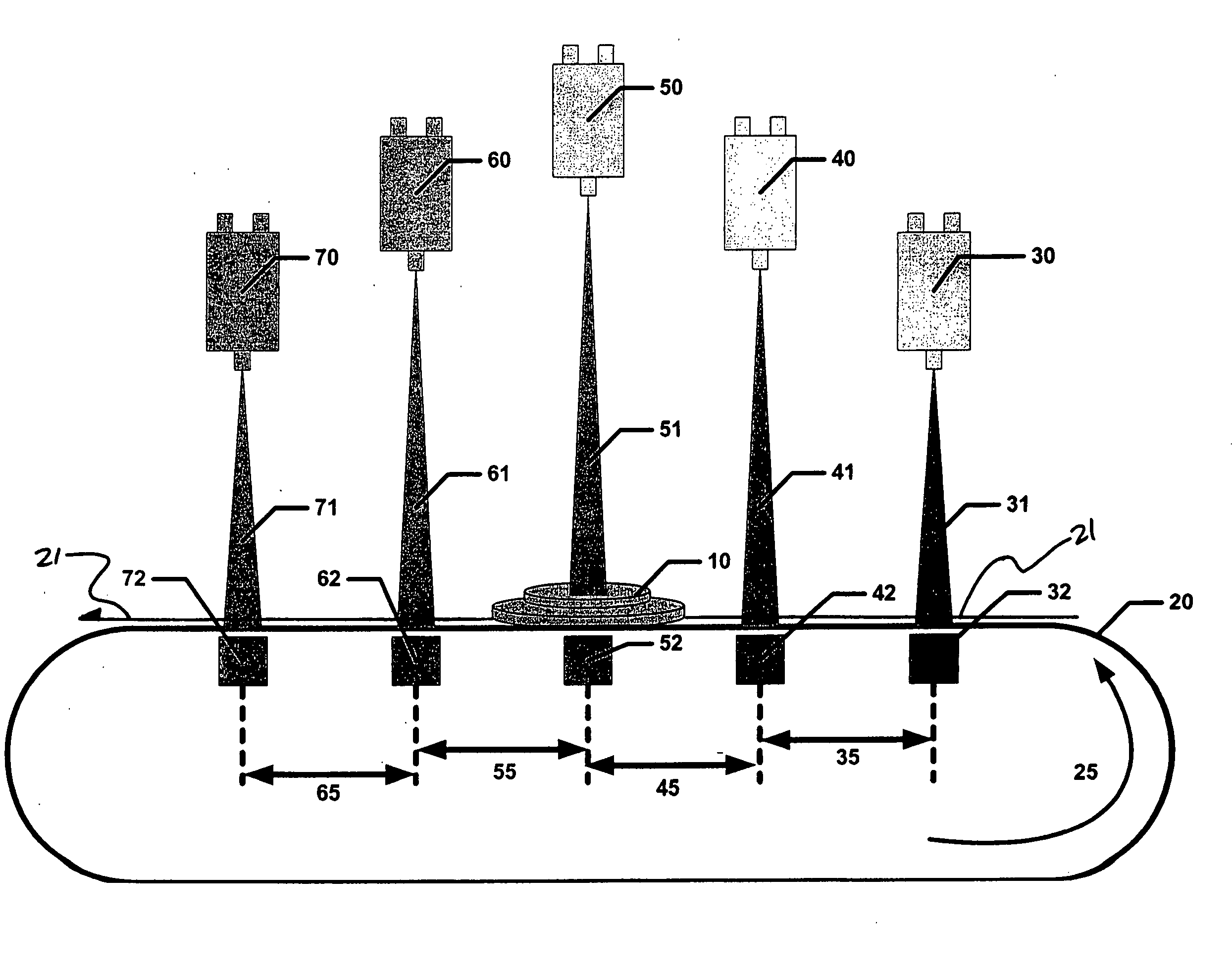
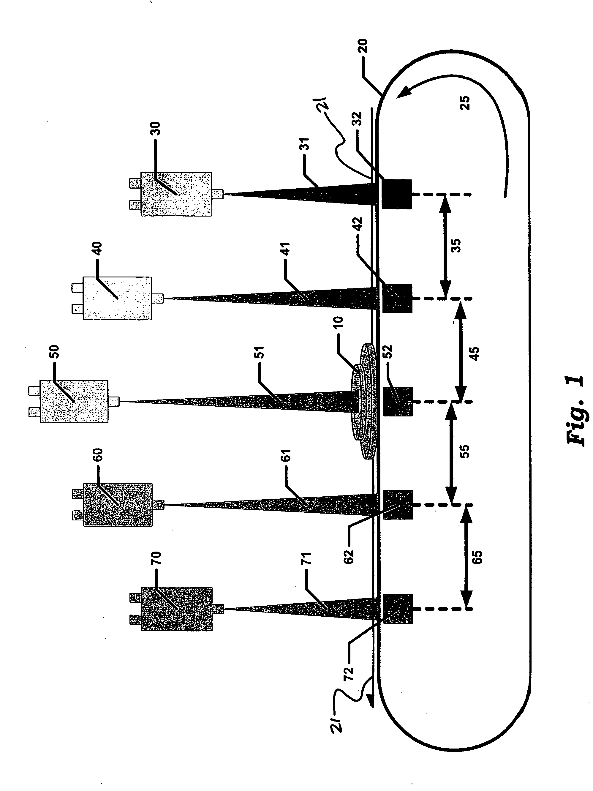
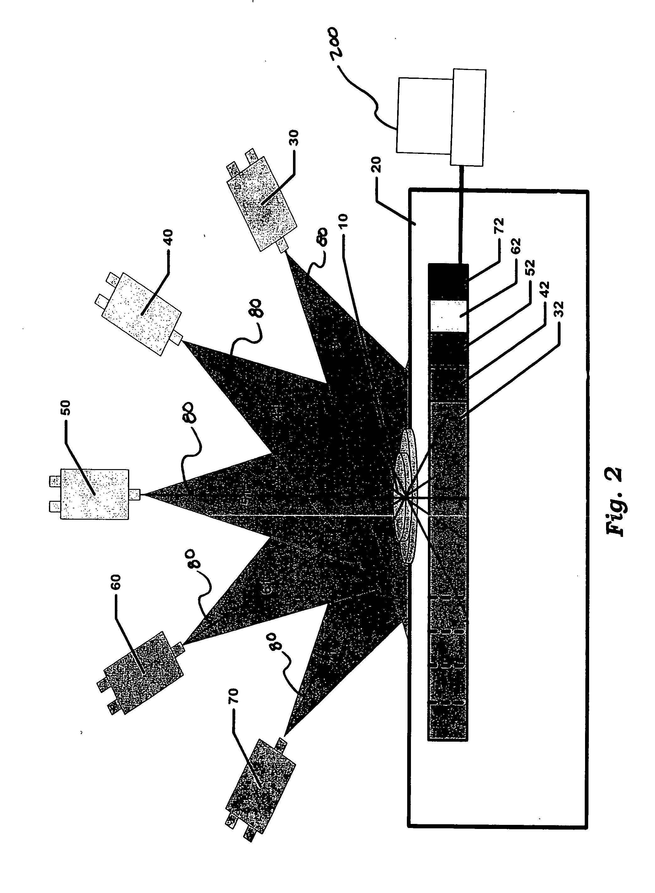
FIG. 1 depicts a side view of a preferred embodiment of the present invention. For simplicity, this figure depicts five X-ray emitter / detector pairs. However, for highly accurate object detection, it is preferred that a greater number of X-ray emitters and detectors be used. In the preferred embodiment, the specimen 10 is transported along a transport path 21 on a conveyor 20 in a direction 25 with a plurality of emitters 30, 40, 50, 60 and 70 directed at various angles toward the transport path 21 of the specimen 10. The plurality of detectors 32, 42, 52, 62 and 72 receive and record the transmitted energy from the plurality of fan-shaped X-ray beams 31, 41, 51, 61 and 71 as the specimen 10 moves through the ima...


PUM


Abstract

A system for detecting embedded objects in a specimen that includes a transport system effecting movement of the specimen relative to an imaging zone along a transport path. The system also includes detector systems arranged to operably image the specimen in the imaging zone. Each detector system includes an emitter, detector, and a primary axis defined between the emitter and detector and that crosses the transport path. Energy from the emitter is directed along the primary axis and transmitted to a unique detector producing a succession of images as there is movement of the specimen relative to the imaging zone. The system further includes a computer system operably connected to the detector systems to receive and combine the succession of images producing a plurality of image slices that are combined as a representation of the specimen for use in detecting embedded objects in the specimen.

Description

FIELD OF THE INVENTION The present invention relates generally to imaging systems and more particularly to using computed tomography to detect embedded objects. BACKGROUND OF THE INVENTION X-ray systems have been used for years as the primary method for bone and cartilage detection. The penetrating nature of X-rays and their variable absorption based on the density of the material make them good candidates for “seeing inside” the parts to be inspected. While X-rays seem to be an ideal solution for inspection within poultry processing facilities, the qualities of chicken breasts and their structural relationship between bone and cartilage make X-ray alone an inadequate tool for properly identifying bones and cartilage. X-rays can simply be described as electromagnetic energy that penetrates objects and experiences absorption or transmission based on the atomic mass of the object. Unfortunately, it is very difficult for X-ray images to distinguish between a thin slice of dense mate...

Claims


Application Information

Patent Timeline
IPC IPC(8): A22B5/00A22C17/00A22C21/00A61B6/03G01N23/04
CPCA22B5/007A22C17/0073A22C21/00A61B6/032G01N2223/419A61B6/4266A61B6/482G01N23/046A61B6/4014
Inventor RETTERATH, JAMES E.LAUMEYER, ROBERT A.
Owner FACET TECH LLC
Why Eureka
Try Eureka