Vehicle suspension systems

a suspension system and vehicle technology, applied in the field of suspension systems, can solve the problems that small power loss can have a significant detrimental effect on rider performance and comfort, and achieve the effects of facilitating squat response, lowering energy loss resulting from squat, and facilitating squat respons

Active Publication Date: 2005-03-31
DW LINK
View PDF20 Cites 30 Cited by
  • Summary
  • Abstract
  • Description
  • Claims
  • Application Information

AI Technical Summary

Benefits of technology

[0016] The current invention relates to new suspension systems for vehicles, for example, bicycles, motorcycles, cars, SUVs, trucks, two wheel vehicles, four wheel vehicles, front wheel suspension vehicles, driven wheel suspension vehicles, and any other kind of vehicle with a suspension system. In certain embodiments of the invention, a suspension system of the invention is capable of facilitating a squat response that lowers the energy loss resulting from squat. In certain preferred embodiments, a suspension system of the invention is capable of lowering energy loss resulting from squat by producing an anti-squat response. An anti-squat response of a suspension system of the invention, in certain embodiments, varies along suspension travel of the vehicle and preferably is higher at the beginning of suspension travel and less thereafter.
[0017] Certain embodiments of the invention comprise a wheel suspension design that uses a tuned squat response to reduce powered acceleration induced suspension movement at tactical points during the driven wheel suspension travel. A vehicle designed to use the preferred embodiment of the invention can accelerate under power with a lower amount of energy loss and a more stable vehicle chassis than known systems.
[0018] Suspension systems of the invention are useful for a variety of vehicles and preferably in human powered vehicles. The average rider of a bicycle or other human powered vehicle can exert only a limited amount of power or energy for a short period of time and an even lesser amount for an extended period of time. Therefore, even a very small power loss can have a significant detrimental effect on rider performance and comfort. The need for a suspension system that can better preserve the rider's energy has therefore become more pressing. The present invention provides suspension system designs for vehicles that reduce energy loss during powered acceleration.

Problems solved by technology

Therefore, even a very small power loss can have a significant detrimental effect on rider performance and comfort.

Method used


Image

  • Vehicle suspension systems
  • Vehicle suspension systems
  • Vehicle suspension systems

Examples


Embodiment Construction

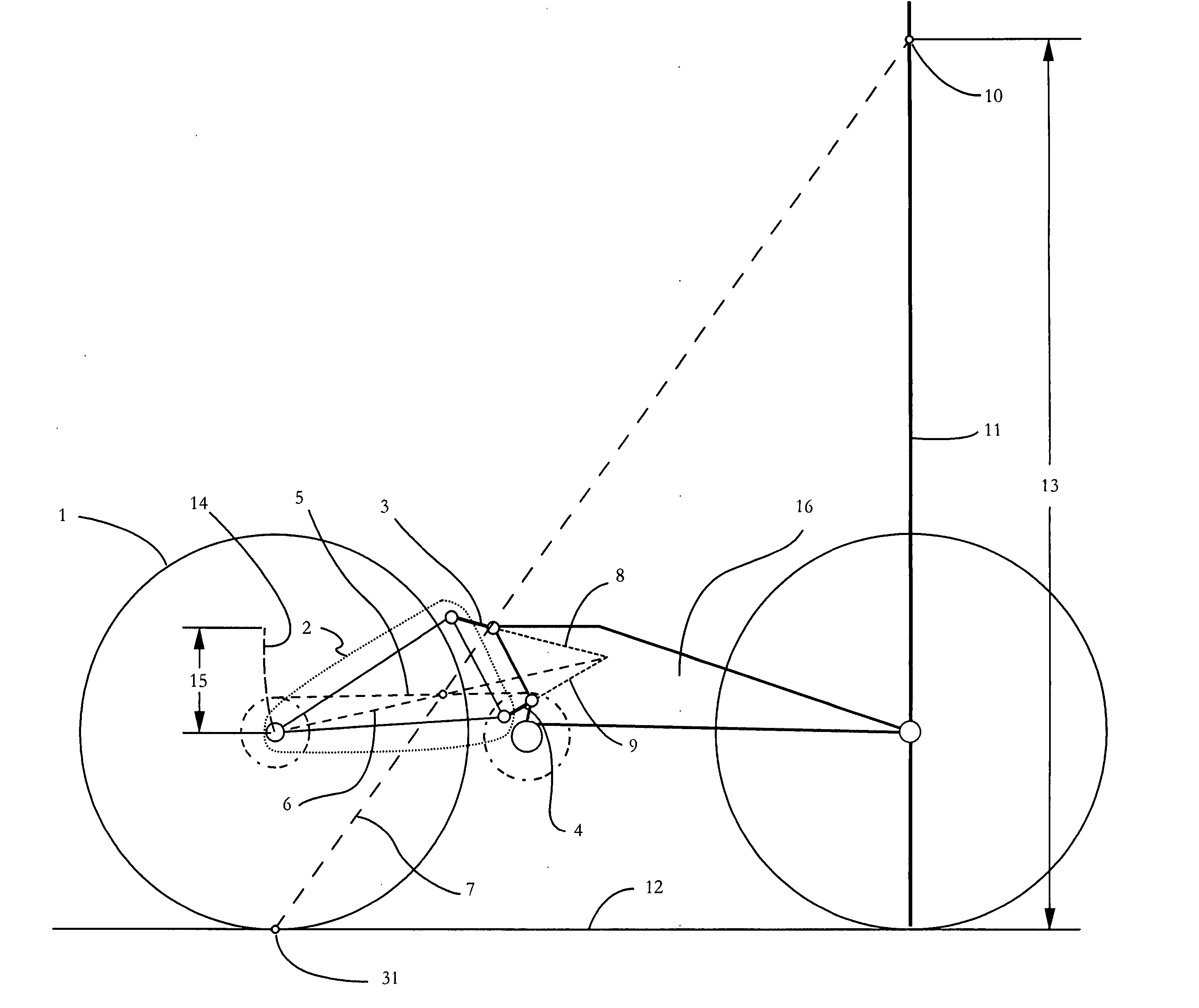
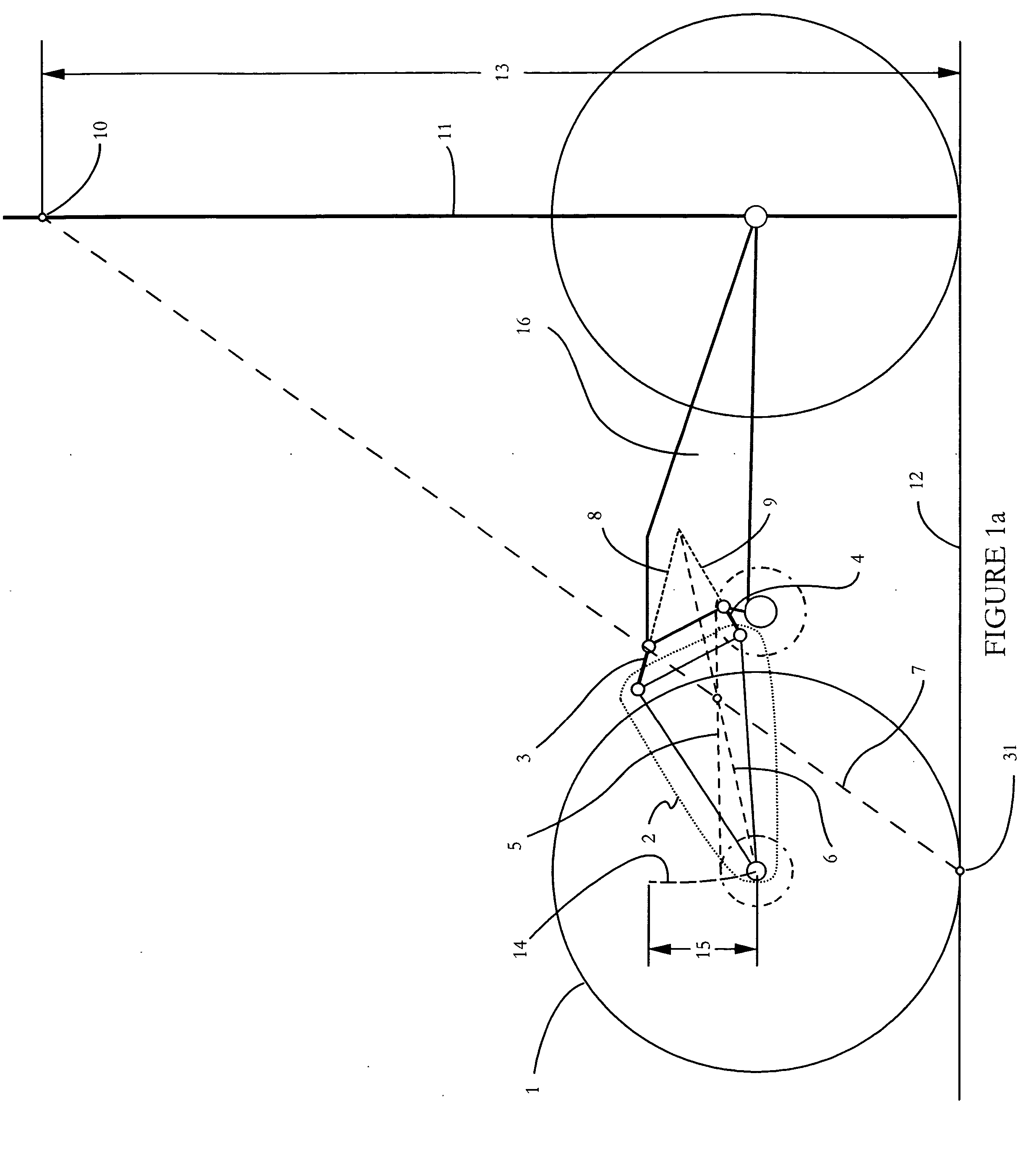
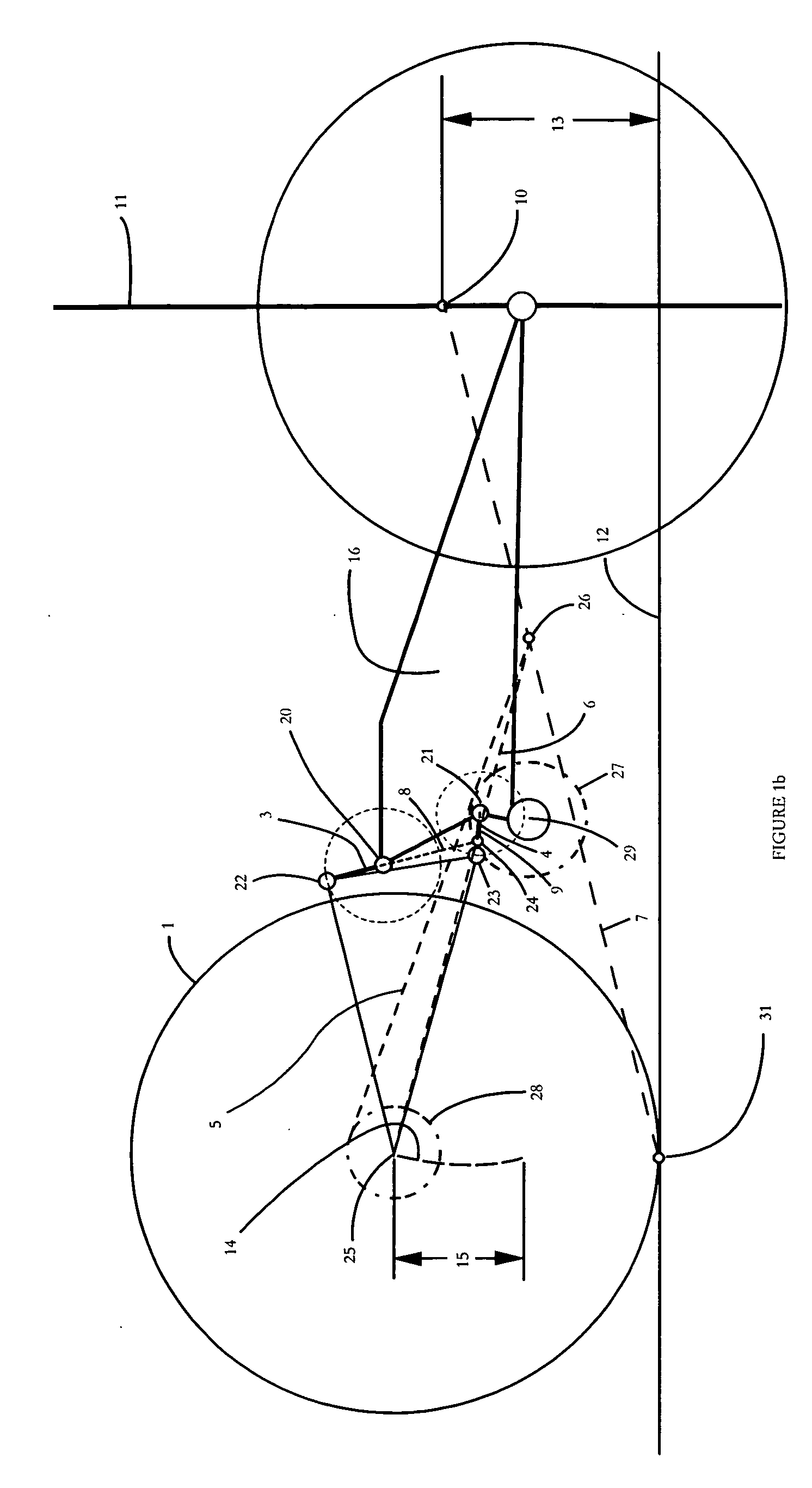
[0028] Vehicles must be accelerated against their environment to propel an operator or rider across terrain. In order to accelerate these vehicles, a certain amount of energy must be exerted and transformed into rotary motion at a wheel or plurality of wheels. Suspended wheeled vehicle energy conversion types are widely varied. Some vehicles like bicycles, tricycles, and pedal cars use converted human energy as the drive unit. Other vehicles use electric motors or combustion engines, as their drive unit. These electric motors and combustion engines extract rotary motion through the controlled release of chemically stored energy.

[0029] Almost all vehicle types use some sort of rotary motion transmission system to transfer rotational force from a drive unit to a wheel or plurality of wheels. A simple bicycle or motorcycle or all terrain vehicle uses a chain or belt to transfer power from a drive unit to a wheel. These chain or belt drive transmissions typically use one sprocket in th...


PUM


Abstract

A wheel suspension system having under powered acceleration a squat response that begins in the realm of anti squat and passes through a point of lessened anti squat at a further point in the travel.

Description

[0001] This application is a continuation in part of U.S. application Ser. No. 10 / 669,412, filed Sep. 25, 2003, which is incorporated herein by reference in its entirety.BACKGROUND [0002] This invention relates to suspension systems capable of reducing or eliminating a squat response. [0003] Automobiles, bicycles, motorcycles, all terrain vehicles, and other wheel driven vehicles are used for various purposes, including transportation and leisure. These vehicles are designed to use a power source to drive through a power transmission system to a wheel or wheels, which transfers rotary motion to the ground via tractive force between a wheel or wheels and the ground. Vehicles are also used to traverse even terrain like paved streets, and uneven terrain like off-road dirt trails. Off road trails are generally bumpier and allow for less wheel traction than paved roads. A bumpier terrain is best navigated with a vehicle that has a suspension system. A suspension system in a vehicle is ai...

Claims


Application Information

Patent Timeline
Patent Type & Authority Applications(United States)
IPC IPC(8): B60GB60G3/02B60G5/00B60G21/045B62KB62K1/00B62K25/20B62K25/26B62K25/28
CPCB60G5/00B60G21/045B60G2200/464B60G2204/143B62K25/286B60G2204/422B60G2300/12B62K25/26B62K25/28B60G2204/421
Inventor WEAGLE, DAVID
Owner DW LINK
Why Eureka
Try Eureka