

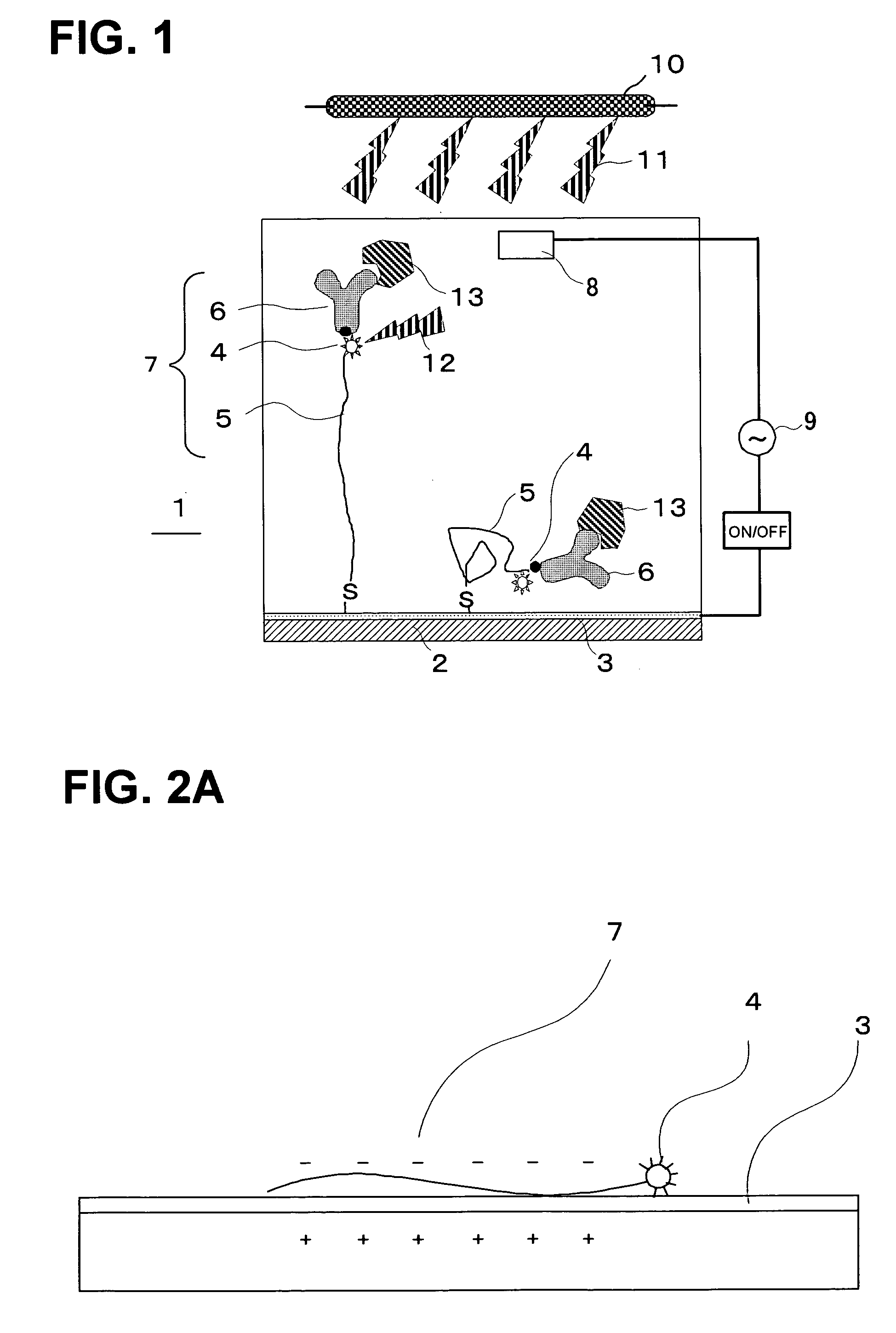
Analyte evaluating device, and method for evaluating analyte
a technology of analyte evaluating device and analyte, which is applied in the direction of optical radiation measurement, fluorescence/phosphorescence, instruments, etc., can solve the problems of complex, small, and inability to integrate analyte evaluating device, and achieve excellent analyte evaluating methods
- Summary
- Abstract
- Description
- Claims
- Application Information
AI Technical Summary
Benefits of technology
Problems solved by technology
Method used
Image

Examples
example 1
[0173] A single-stranded oligonucleotide with a fluorescent-pigment label introduced to the 5′ terminal was synthesized and reacted with a polished Au electrode at room temperature for 24 hours so as to make the single-stranded oligonucleotide bound to the Au electrode as shown in FIG. 9. The fluorescent-pigment label may be introduced to both ends of the single-stranded oligonucleotide. It may also be introduced to a 3′ terminal of the chain. Oligonucleotide strands were kept on the Au electrode in a circular shape having a diameter of 1 mm. This fluorescent pigment was activated by light, extinguished the fluorescence when it was sufficiently near the metal surface, and emitted fluorescence when it was sufficiently distant from the metal surface.
[0174] The light irradiation device was placed at an angle of 45° from the Au electrode and set to allow incident rays to reach all over the electrode surface. In addition, the light-receiving optical fibers (a fluorescence detection devi...
example 2
[0178] The same measurement was conducted as EXAMPLE 1 except that the diameter of the Au electrode was 2 mm, twice the size of the one in example 1, as shown in FIG. 12, that was sufficiently large as compared with the inner diameter of the light receiving optical fibers. The results are shown in FIG. 5.
[0179] In this case, the detachment of oligonucleotides occurred similarly as the electric field was applied, and the increase of fluorescence intensity was observed. After that, since the diameter of the Au electrode was sufficiently larger than the inner diameter of the optical fibers, diffusion around the light-receiving optical fibers was retarded, with the result that a time ts for the fluorescence to be saturated appeared. Then, as time went by, the oligonucleotides were diffused to the surroundings, and decrease of the fluorescence intensity was observed.
[0180] Since the oligonucleotides that had been once electrostatically repulsed spread out of the light detection area by...
example 3
[0181] The measurement of the change of fluorescence intensity was conducted using the same setup as the one employed for EXAMPLE 1 except for the electric filed applied to the electrode and the salt concentrations.
[0182] Various kinds of DC negative electric fields (−200 mV, −400 mV, −600 mV, −800 mV, and −1000 mV) were applied to the electrode, and the salt (NaCl) concentration was varied (0 mM, 70 mM, 280 mM and 990 mM), with a constant tris buffer concentration of 10 mM. The change of fluorescence intensity is shown in FIG. 6. The total salt concentrations were 10 mM, 80 mM, 290 mM, and 1,000 mM.
[0183] At 10 mM and 80 mM salt concentrations, a relatively large fluorescence intensity was observed from a relatively low electric field of −600 mV. A maximum fluorescence intensity was observed at a point of negative electric field of −800 mV at a salt concentration of 290 mM.
[0184] From this, it is understood that it is possible to observe the fluorescence from a relatively low el...
PUM
| Property | Measurement | Unit |
|---|---|---|
| diameter | aaaaa | aaaaa |
| diameter | aaaaa | aaaaa |
| inner diameter | aaaaa | aaaaa |
Abstract
Description
Claims
Application Information