Silicone binders for investment casting

Active Publication Date: 2005-03-31
GENERAL ELECTRIC CO
View PDF29 Cites 53 Cited by
  • Summary
  • Abstract
  • Description
  • Claims
  • Application Information

AI Technical Summary

Benefits of technology

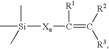
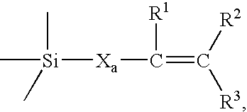
Disclosed herein is a green product for use in fabricating a ceramic article, comprising a ceramic powder immobilized within a silicone matrix, wherein the silicone matrix comprises one or more cross linked or polymerized silicone monomer

Problems solved by technology

Investment casting cores made using low pressure casting techniques generally suffer from poor mechanical properties.
Poor mechanical properties resulting from the low pressure casting process causes difficulty in ejecting cast parts from the metal die following curing.
This firing step can lead to thermally induced flaws in the core, reducing its strength and increasing production scrap that continues throughout the metal casting process.
Dimensional control of the silica core is difficult for at least two reasons.
First, crystalline-based silica materials are susceptible to Martensitic-type phase changes during the casting process.
Otherwise, the core may crack once it is cooled down while still in the associated mold.
Secondly, thermal expansion differences between the silica core and the associated mold are typically very large.
Accordingly, it is difficult, if not impossible, to tightly fix the silica core within an associated mold without rendering the silica core susceptible to cracking.
Unfortunately, cores comprised of alumina based ceramics are known to exhibit excessive thermal expansion and poor crush behavior.
Such behavior is unacceptable for applications where dimensional precision is required during manufacture, such as in the production of directionally solidified metal eutectic alloys and superalloys, which are typically used for manufacturing of turbine components.
Moreover, alumina cores are typically removed using an autoclave operation, which adds considerable expense to the process.
Further, shrinkage with a concomitant decrease in poro

Method used


Image

  • Silicone binders for investment casting
  • Silicone binders for investment casting
  • Silicone binders for investment casting

Examples


example 1

In this example, a 38% by volume ceramic article was cast using a mixture of 1,3,5,7-tetravinyl-1,3,5,7-tetramethylcyclotetrasiloxane and a poly[(methylhydrogen)-co-(dimethyl)]siloxane. In this case, the vinyl to silicone hydride molar ratio was maintained at 1:1. The ceramic was a mixture of amorphous silica and zircon. A 422 gram batch was prepared by mixing the various constituents for 15 seconds in a high-shear mixer operating at 2,500 rpm. Following mixing, the batch was degassed using a rotary vacuum mixer for 5 minutes operating at roughly 50 torr and 60 rpm.

The batch was then cast into a mock investment casting core by infiltrating a specially-designed steel die with the slurry at roughly 10 psi pressure. Following casting, the part was cured at 100° C. for roughly 30 minutes prior to part ejection. Following ejection, the part was cooled to room temperature.

Following casting, the part was fired in air at a rate of 10° C. per hour to a temperature of about 600° C., with...

example 2

Ceramic test bars were cast using a mixture of 1,3,5,7-tetravinyl-1,3,5,7-tetramethylcyclotetrasiloxane and 1,3,5,7-tetramethylcyclotetrasiloxane in a molar ratio of 1:1. The ceramic was a mixture of amorphous silica and zircon, present at 40% by volume. A 177.8 gram batch was prepared by mixing the constituents for 10 seconds in a high-shear mixer at 2,500 rpm. Following mixing, the batch was degassed in a rotary vacuum mixer for 5 minutes at roughly 50 torr and 60 rpm.

The batch was then loaded into disposable transfer syringes, and hand injected into a custom designed steel casting die. Approximate die opening dimensions were 0.1″×0.5″×5″. Following casting, the articles were cured at 50° C. for roughly 90 minutes prior to removal. The resultant article had a smooth hard surface, was strong and resilient, and could be readily handled without breaking.

example 3

Ceramic test bars were cast using a mixture of 1,3,5,7-tetravinyl-1,3,5,7-tetramethylcyclotetrasiloxane and a hydride functional silicate resin corresponding to Formula (VII), containing hydridodimethylsiloxy and silicate units in a molar ratio of 2:1. The total silicon hydride to vinyl molar ratio was 1:1. The ceramic was a mixture of amorphous silica and zircon, present at 40% by volume. A 177.8 gram batch was prepared by mixing the constituents for 10 seconds in a high-shear mixer at 2,500 rpm. Following mixing, the batch was degassed in a rotary vacuum mixer for 5 minutes at roughly 50 torr and 60 rpm.

The batch was then loaded into disposable transfer syringes, and hand injected into a custom designed steel casting die. Approximate die opening dimensions were 0.1″×0.5″×5″. Following casting, the articles were cured at 50° C. for roughly 90 minutes prior to removal. The resultant article had a smooth hard surface, was strong and resilient, and could be readily handled without ...


PUM

PropertyMeasurementUnit
Kinematic viscosityaaaaaaaaaa
Temperatureaaaaaaaaaa

Abstract

A green product for use in fabricating a ceramic article comprises a ceramic powder immobilized within a silicone matrix, wherein the silicone matrix comprises one or more cross linked or polymerized silicone monomers and/or oligomers, wherein the one or more cross linked or polymerized silicone monomers and/or oligomers have a alkenyl reactive functional group and a hydride reactive functional group. Processes for forming a green product and a ceramic core with the silicone monomers and/or oligomers are also disclosed.

Description

BACKGROUND This disclosure generally relates to investment casting, and more particularly, relates to silicone-based binders for use in forming the ceramic cores and shell molds employed in investment casting. The manufacture of gas turbine components, such as turbine blades and nozzles, requires that the parts be manufactured with accurate dimensions having tight tolerances. Investment casting is a technique commonly employed for manufacturing these parts. The dimensional control of the casting is closely related to the dimensional control of a ceramic insert, known as the core, as well as the mold, also known as the shell. In this respect, it is important to be able to manufacture the core and shell to dimensional precision corresponding to the dimensions of the desired metal casting, e.g., turbine blade, nozzle, and the like. In addition to requiring dimensional precision in the casting of the ceramic core, the production of various turbine components requires that the core no...

Claims


Application Information

Patent Timeline
IPC IPC(8): C08K3/18C08K3/34C08K3/38C08L83/04
CPCC08G77/045C08G77/12C08G77/20C08G77/70C08L83/04C08K3/34C04B35/14C04B35/62635C04B35/62665C04B35/6269C04B2235/3206C04B2235/3217C04B2235/3222C04B2235/3225C04B2235/3244C04B2235/3248C04B2235/3418C04B2235/3463C04B2235/36C04B2235/3826C04B2235/3847C04B2235/386C04B2235/3873C04B2235/40C04B2235/401C04B2235/402C04B2235/404C04B2235/483C04B2235/6027C04B2235/6562C04B2235/661C04B2235/80
Inventor MCNULTY, THOMASLEMAN, JOHN
Owner GENERAL ELECTRIC CO
Why Eureka
Try Eureka