Storage system and storage controller

a storage controller and storage system technology, applied in the direction of micro-instruction address formation, memory adressing/allocation/relocation, instruments, etc., can solve the problems of increasing the number of storage controllers that make up the storage system, introducing cost, and ineffective utilization of old storage controllers. to achieve the effect of effectively utilizing memory resources

Active Publication Date: 2005-03-31
HITACHI LTD
View PDF99 Cites 83 Cited by
  • Summary
  • Abstract
  • Description
  • Claims
  • Application Information

AI Technical Summary

Benefits of technology

[0010] The present invention is made in consideration of the above problem points, and one object of the present invention is to provide a storage system and a storage c

Problems solved by technology

However, no storage controller of the old type can be effectively utilized and introducing cost is increased.
When it is intended that the storage controller of the old type and the storage controller of the new type coexist, the number of storage controllers constituting the storage system is increased and it takes much time

Method used


Image

  • Storage system and storage controller
  • Storage system and storage controller
  • Storage system and storage controller

Examples


first embodiment

[0039] 1. First Embodiment

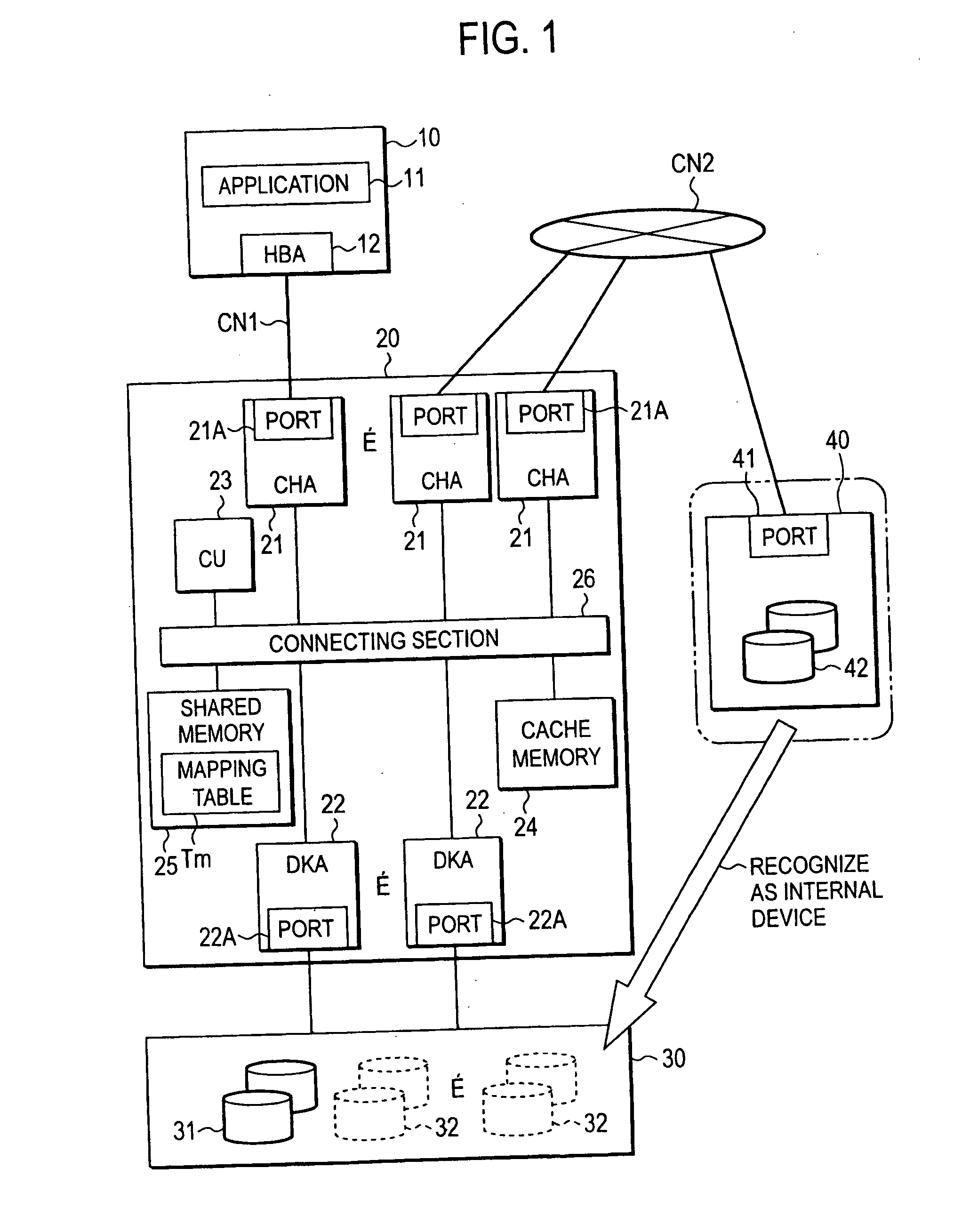
[0040]FIG. 1 is a block diagram showing the construction of a main portion of a storage system in this embodiment.

[0041] For example, a host device 10 is a computer device having information processing resources such as a CPU (Central Processing Unit), a memory, etc., and is constructed as a personal computer, a work station, a main frame, etc. For example, the host device 10 has an unillustrated information input device such as a keyboard switch, a pointing device, a microphone, etc., and an unillustrated information output device such as a monitor display, a speaker, etc. For example, an application program 11 such as database software, etc. using a memory area provided by a first storage controller 20, and an adapter 12 for getting access to the first storage controller 20 through a communication network CN1 are arranged in the host device 10.

[0042] The host device 10 is connected to the first storage controller 20 through the communication network CN1...

second embodiment

[0088] 2. Second Embodiment

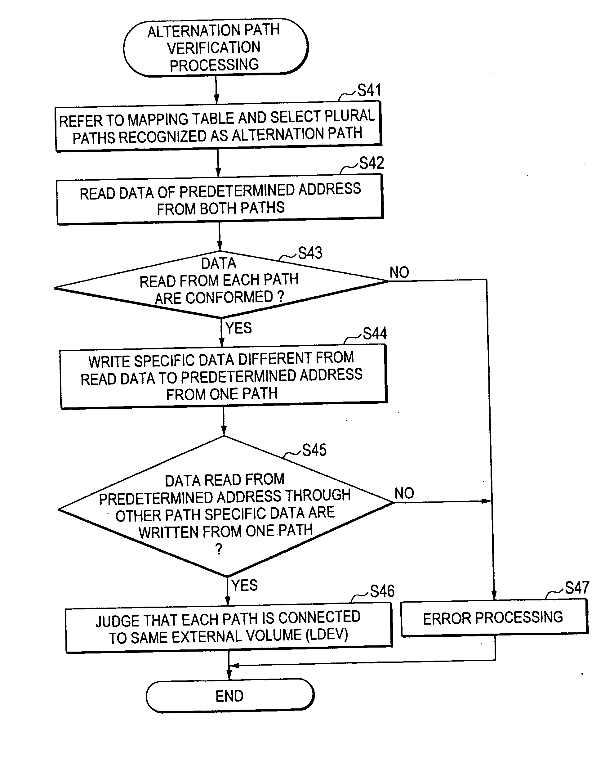
[0089] The second embodiment of the present invention will next be explained with reference to FIG. 9. The features of this embodiment are that the alternating path structure arranged in the second storage controller 40 is verified.

[0090]FIG. 9 is a flowchart schematically showing verification processing of the alternating path structure executed by the first storage controller 20. The first storage controller 20 selects one set of access data paths (normally two access data paths) recognized as the alternating path by referring to the mapping table Tm (S41).

[0091] Next, the first storage controller 20 reads data from a predetermined address through each selected path (S42), and judges whether the data read from each path are conformed or not (S43). When the data read from both paths are conformed to each other (S43: YES), it is possible to tentatively judge that the alternating path structure is constructed. However, the possibility that each path is co...


PUM


Abstract

Memory resources are effectively utilized by visually setting an external memory resource as an internal memory resource. A first storage controller has a multilayer memory hierarchy constructed by LDEV (logical device) connected from LUN, and VDEV (virtual device) connected to the lower order of the LDEV. At least one of the VDEVs is constructed by mapping the memory resources arranged in external storage controllers. The functions of a stripe, RAID, etc. can be added in the mapping. Various kinds of functions (remote copy, variable volume function, etc.) applicable to the normal internal volume can be also used in a virtual internal volume by using the external memory resource as the virtual internal memory resource so that the degree of freedom of utilization is raised.

Description

CROSS-REFERENCES TO RELATED APPLICATIONS [0001] This application relates to and claims priority from Japanese Patent Application No. 2003-337239 filed on Sep. 29, 2003, the entire disclosure of which is incorporated herein by reference. BACKGROUND OF THE INVENTION [0002] The present invention relates to a storage system and a storage controller. [0003] For example, in a database system for treating a large amount of data such as a data center, etc., the data are managed by using a storage system constructed separately from a host computer. This storage system is constructed from e.g., a disk array device, etc. The disk array device is constructed by arranging many memory devices in an array shape, and is also constructed on the basis of e.g., RAID (Redundant Array of Independent Inexpensive Disks). At least one or more logical volumes (logical units) are formed in a physical memory area provided by a memory device group. This logical volume is provided to the host computer (more spe...

Claims


Application Information

Patent Timeline
IPC IPC(8): G06F3/06G06F12/00G06F12/08G06F12/16
CPCG06F3/0607G06F3/067G06F3/0664G06F3/0635G06F12/0824G06F12/1009
Inventor TAMURA, KEISHINAKAYAMA, SHINICHIUCHIUMI, KATSUHIRO
Owner HITACHI LTD
Why Eureka
Try Eureka